101-091 13
FGR006 – Version 3.0
–
FGR006 FINGERPRINT & PROXIMITY READER
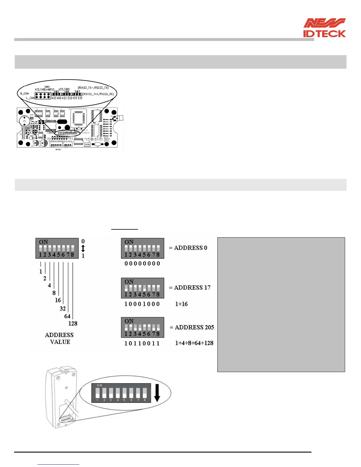
5. Communication
The communication setting is defaulted to RS422.
If you need the change of the mode of the communication, FGR006
(FGR006EX) must set on the links on the MAIN PCB.
Changing this jumper setting requires the use of a soldering iron.
CAUTION: Damage to the PCB will void warranty.
5.1 Address Setting for RS485/RS422 Communication
There is 8bit DIP SW for address setting and it turns to 8bit binary code as below and each bit has fixed
address value, the address is calculated the sum value of each bit set to “1” position.
Example
NOTE: To select the address switch
to “ON” switch it down.
NOTE: Address Setting
If used with a Ness – IDTeck iCON
control panel with Dual Pro software
then the address must start at 33 ((i.e 1
& 6 down)) regardless of how many
controllers you have online.
If used with a Ness – IDTeck iTDC
control panel with iTDC Pro software
then the address must start at 100. (i.e 3,
6 & 7 down) regardless of how many
controllers you have online.
If used with 3
rd
party controllers refer to
your vender for address instructions