101-091 8
FGR006 – Version 3.0
–
FGR006 FINGERPRINT & PROXIMITY READER
4. INSTALLATION
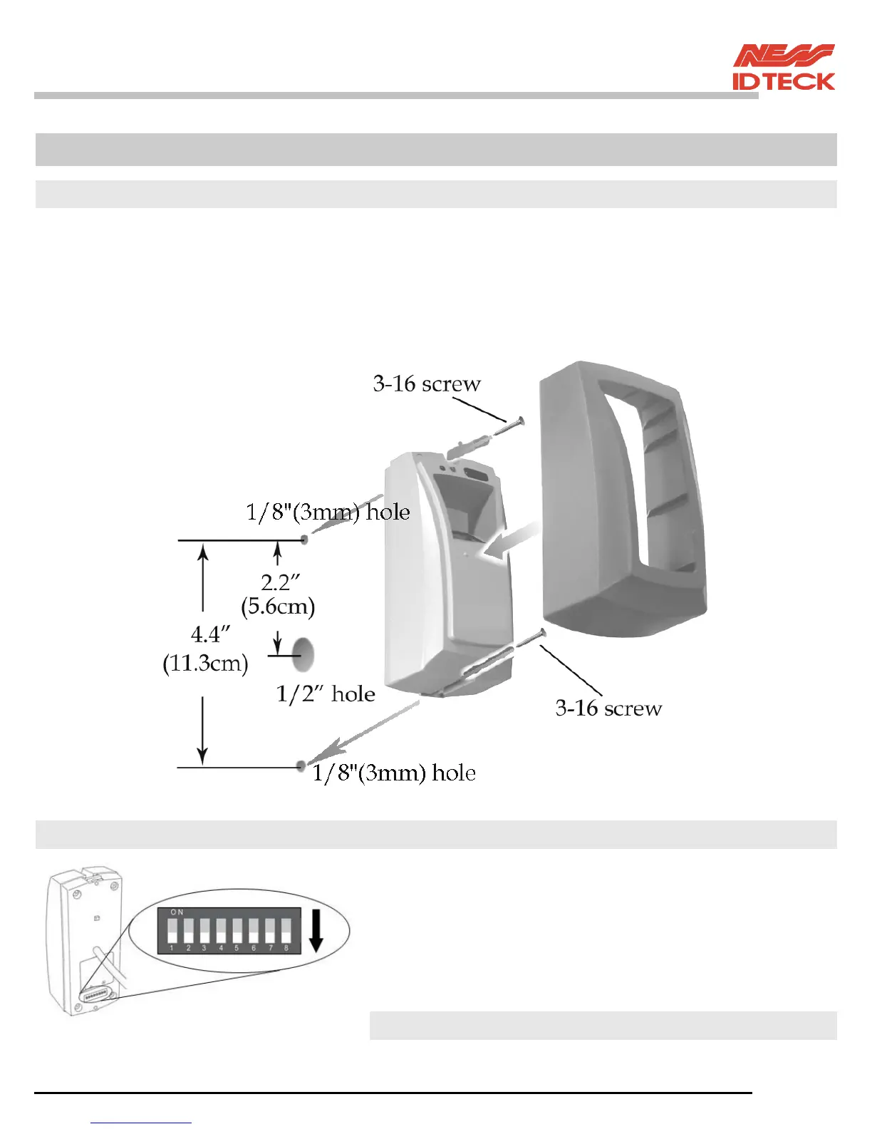
4.1 Mullion/Wall Mount
4.1.1 Drill two Ø1/8"(3mm) holes, 4.4"(113mm) apart in vertical and drill one Ø1/2" hole for
the reader cable 2.2"(56mm) apart from the top hole.
4.1.2 Connect wires between the control panel and FGR006 reader then put reader
cable into the centre hole and install the main unit by using two 3-16 screws.
4.1.3 Put bezel into the main unit then push bezel until you hear the locking sound.
4.2 System Initialisation
You can H/W initialise using DIPswitch.
First, turn on the system power and turn off all Dipswitches.
Set the DIPswitch after an initialisation completion.
* DIP Switch use for address of RS422/RS485 communication.
An Initialisation situation refers to the "7.Operation Indication
of Reader / Register" of manual.