25
USB Micro B
USB Micro A
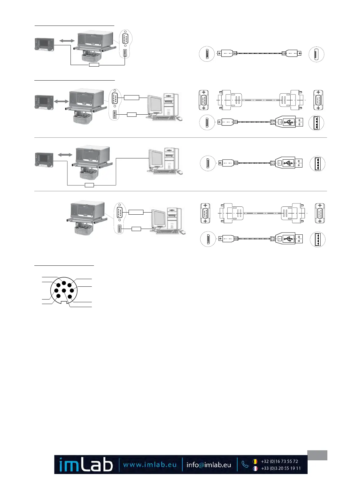
Connection WiCo to Station:
Fig. 32
Micro B
Micro A
Connection the device to PC:
RS 232
USB
A
USB Micro B
USB A
9-pin RS 232 9-pin RS 232
or
USB A
A
USB Micro B
USB A
RS 232
USB
or
A
9-pin RS 232 9-pin RS 232
USB Micro B USB A
Fig. 33
Micro B
Micro B
Micro B
Multifunction interface:
1 M1 Output Valve + (+24Vdc/max� 0�8A)
2 M1 Output Valve -
3 M2 Output Alarm/Switch 1 (max� 30Vdc/ac/max� 1A)
4 M2 Output Alarm/Switch 2
5 M3 Input standby + (+5V ca� 10mA)
6 M3 Input standby - (0V only for Standby)
7 --- (reserved for later use, do not connect!)
8 --- (reserved for later use, do not connect!)
1
2
3
4
5
6
7
8
Fig. 34