OPERATION
LDC-3900 Front Panel
10_15 LDC-3900 Series 13
CHAPTER 2
(I
TE
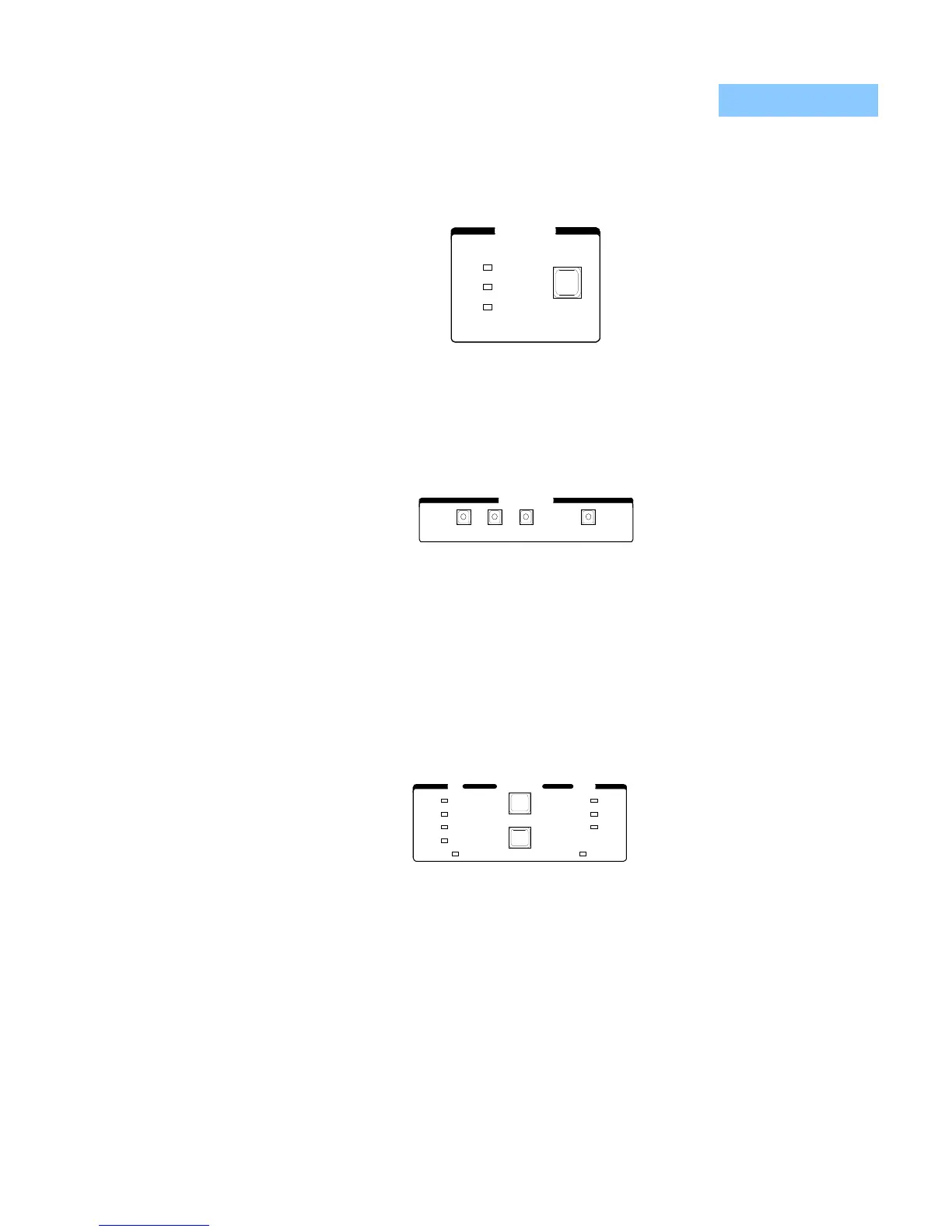
) control modes. The LED Indicators show the selected mode. (For more
information, see TEC Mode Section on page 18).
Figure 2.7 TEC Mode
The TEC Display switch section is used to select the measured T, R, or I
TE
values
or the set point value. The set point is determined by the TEC Mode selection.
(For more information, see TEC Display Switch Section on page 19).
Figure 2.8 TEC Display
When the (Adjust) TEC mode is selected, the TEC set point may be displayed and
adjusted (automatically) by simply turning the Adjust Knob. (For more information,
see TEC Mode Select on page 19).
The TEC Parameters are TE current limit (LIM I
TE
), high temperature limit (LIM
T
HI
), constants (CONST) for converting from sensor measurements to
temperature, and control loop gain (Gain). (For more information, see TEC
Parameter Section on page 21).
Figure 2.9 TEC Parameters
When the CONST parameter is selected, the constants C1, C2, and C3 are
sequenced by pressing the (Parameter) Select switch, and a corresponding
message of "1", "2" or "3" will be shown on the Laser display. The constant values
will be shown on the TEC display.
PARAMETER LASERTEC
CAL PD
LIM P
LIM I
RECALL
SELECT
SET
LIM I
LIM T
CONST
GAIN
SAVE
HI
TE

 Loading...
