OPERATION
LDC-3900 Front Panel
26 LDC-3900 Series
CHAPTER 2
Laser Mode Select
The (Laser Mode) Select switch is used to select one of the three available Laser
operating modes. When a mode is selected, the corresponding LED becomes lit.
If the (Laser Mode) Select switch is pressed repeatedly, the modes are cycled
through in the order I, P, I
HBW
, and back to I, and so on, with the appropriate Mode
Indicator being lit.
Laser Mode Indicators
The I Indicator becomes lit when the unit is in the constant current control mode.
When constant I mode is selected, the Laser output is controlled to the constant I
set point value.
The P Indicator becomes lit when the unit is in constant optical power control
mode. When constant P mode is selected, the Laser output is controlled to the
constant I
PD
(monitor PD current) or P
PD
(monitor PD power, when the CAL PD
value is non-zero) set point value.
The I
HBW
Indicator becomes lit when the unit is in high bandwidth constant current
control mode. When constant IHBW mode is selected, the Laser output is
controlled to the constant I set point value.
Laser Display Switch Section
The Laser Display switch section is used to select the Laser display mode. Either
the set point or measured I (laser current), I
PD
(monitor PD current), or P
PD
(monitor PD power), or measured V (laser voltage) values may appear on the
Laser display. The set point is determined by the Laser Mode selection.
Any of the measured Laser values may be displayed by pressing the desired
Laser Display switch. When a measurement display mode (I, I
PD
, P
PD
, or V) value
is selected by pressing its switch, the (Laser Display) Set Indicator LED will go off
(if it was previously on).
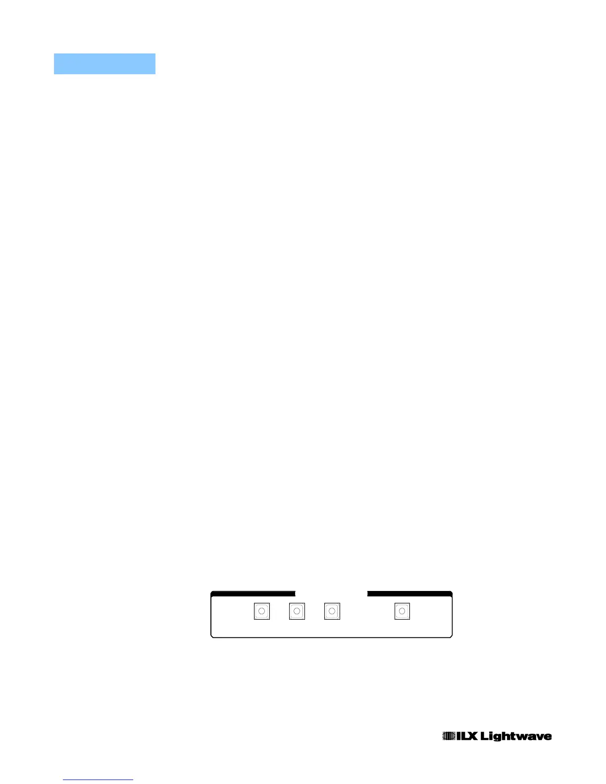
Refer to Figure 2.12 on page 15 during the discussion of the Laser Display switch
section features.
Figure 2.21 LDC-3900 Laser Display Switch Section
LASER DISPLAY
SETVI PDI /P PD

 Loading...
