OPERATION
LDC-3900 Front Panel
10_15 LDC-3900 Series 15
CHAPTER 2
selected mode. Note - not all modes are available with all modules. In that case,
only the valid modes may be selected.
Figure 2.11 Laser Mode
A constant I
PD
mode may be used when P mode is selected, and the CAL PD
parameter value is set to zero.
The Laser Display switch section is used to select the measured I, IPD, or PPD
values or the set point value. The displayed set point is determined by the Laser
Mode selection.
Figure 2.12 Laser Display
The Laser Parameters are Laser current limit (LIM I) for output, laser light power
limit (LIM P), and monitor photodiode responsivity (CAL PD) for converting from
monitor current to light power.
Figure 2.13 Laser Parameters
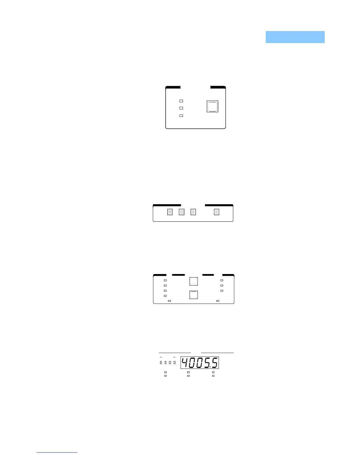
The Laser Display is used to show Laser control (measured and set point) and
parameter values. It may also display errors which relate to Laser operation.
Figure 2.14 Laser Display
LASER DISPLAY
SETVPDI
I /P
PD
PARAMETER LASERTEC
CAL PD
LIM P
LIM I
RECALL
SELECT
SET
LIM I
LIM T
CONST
GAIN
SAVE
HI
TE
CHANNEL
4321
LASER
INTLK/ENBL
ERROR
OUTPUT SHORTED
OPEN CIRCUIT
POWER LIMIT
CURRENT LIMIT
W
mA
V
mW
A

 Loading...
