REMOTE OPERATION
ANSI/IEEE-488.2 Definitions
10_15 LDC-3900 Series 45
CHAPTER 3
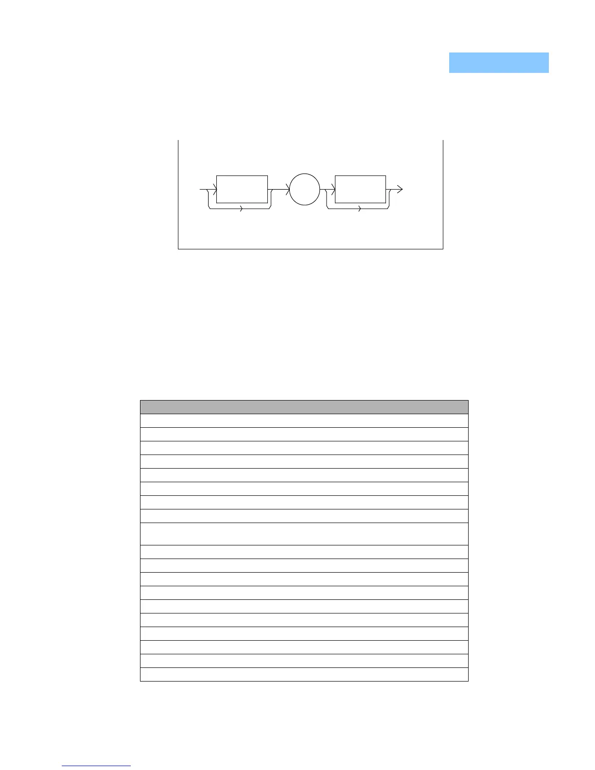
diagram for a <PROGRAM UNIT SEPARATOR> is shown in Figure 3.8 on page
45.
Figure 3.8 <PROGRAM DATA SEPARATOR> Syntax Diagram
Default Parameters
There are no default values for omitted parameters. If a command is expecting a
parameter and none is entered, an error will be generated. However, if a reset is
performed via a *RST command (or a RCL 0 command), the following parameters
will be set to the default state shown in Table 3.1 on page 45.
Table 3.1 State of the LDC-3900 After *RST
LDC-3900 Condition
GPIB in local via front panel; in remote via GPIB
ParameterS not selected
TEC and/or Laser adjust not selected
TEC output off
TEC Display enabled, in T mode
Constant T mode selected
TEC Display showing actual temperature (if TEC module exists)
Temperature Set Point = 0°C
Resistance/Reference Set Point = 1 or 1 A or 1 mV (depending on the setting of the
SENSOR Select switch)
ITE Set Point = 0
LIM ITE set to 25% of maximum
LIM THI set to 99.9°C
TEC STEP value = 1
TEC Tolerance values = 0.2°C, 5 seconds
GAIN = 30
C1 = 1.125 (x 10
-3
)
C2 = 2.347 (x 10
-4
)
C3 = 0.855 (x 10
-7
)
CAL PD = 0.0
<white
space>
<white
space>
,

 Loading...
