OPERATION
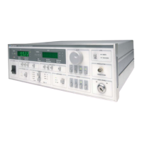
LDC-3900 Front Panel
10_15 LDC-3900 Series 19
CHAPTER 2
constant temperature (T), constant thermistor resistance/linear sensor reference
(R), or constant TEC current (I
TE
) mode.
Figure 2.16 LDC-3900 TEC Mode Section
The corresponding (Adjust) TEC indicator must be orange before adjusting the
parameters of the TEC Mode functions. Refer to Figure 2.7 on page 13 for the
discussion of the features in the TEC Mode section of the LDC-3900 Modular
Laser Diode Controller front panel.
TEC Mode Select
The Select switch is used for selecting one of the three TEC modes available. The
selected mode will be indicated by the corresponding lit LED Indicator.
If the Select switch is pressed repeatedly, the TEC modes are cycled through in
the order T, R, I
TE
, then back to T, and so on, with the appropriate TEC Mode
Indicator being lit.
TEC Mode Indicators
The T indicator becomes lit when the unit is in the temperature control mode.
When the unit is in constant temperature mode, the TEC is controlled to the
constant T set point value.
The R indicator becomes lit when the unit is in the sensor resistance/reference
control mode. When the unit is in constant R mode, the TEC is controlled to the
constant R set point value (in kW, for back panel SENSOR Select settings of 100
or 10 mA thermistor sensor currents; in mV, for the LM335; in mA, for the AD590
setting; and kW for the RTD).
The ITE indicator becomes lit when the unit is in the TEC drive current control
mode. When the unit is in constant TEC current mode, the TEC is controlled to the
constant I
TE
set point value.
TEC Display Switch Section
The TEC Display switch section is used to select the TEC display mode. Either
the set point or measured T (temperature), R (resistance/reference), or I
TE
(TEC

 Loading...