OPERATION
LDC-3900 Front Panel
16 LDC-3900 Series
CHAPTER 2
The LAS Channel indicators show which LAS channel may be adjusted (LED lit)
and whose measurements are displayed. They also blink if an error occurs on a
LAS channel which is not presently selected for adjustment.
The Laser Error Indicators become lit when the corresponding Laser conditions
occur. (For more information, see Laser Error Indicators on page 30). The Output
SHORTED light comes on whenever the selected Laser output is off.
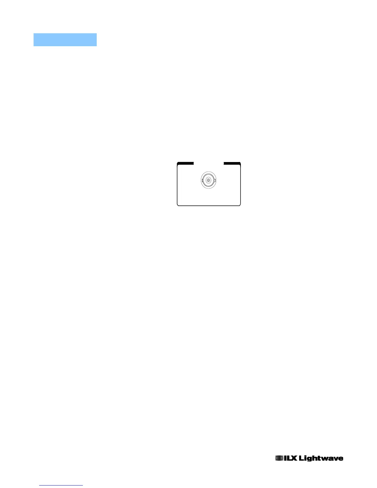
The Modulation section is used for front panel connection of a DC to 500 kHz
modulation signal which may be applied to a laser (via a jumper to a laser current
source module) on the back panel of the LDC-3900.
Figure 2.15 Modulation
Automatic Laser Shutoff Conditions
• Laser Power Limit (may be defeated via GPIB, using the LAS:ENAB:OUTOFF command)
• Laser Interlock/Laser Enable Switch State Changed (see Laser module instruction manual)
• Laser Open Circuit (While Output On)
• TEC High Temperature Limit Condition (may be defeated via GPIB, using the
LAS:ENAB:OUTOFF command)
• Laser mode changes wile the output is on.
GPIB Section
The GPIB section is located in the top right corner of the LDC-3900 Modular Laser
Diode Controller front panel (see Figure 2.1 on page 10). This section contains the
LOCAL switch and the REMOTE and TALK/LISTEN indicators. The LOCAL
switch is used for several functions as described below.
Sending any command over the GPIB bus automatically puts the instrument in
REMOTE mode. The REMOTE indicator identifies when the instrument is in
remote operation mode. When the instrument is in REMOTE mode, pressing the
LOCAL switch returns the instrument to LOCAL control mode unless a Local
Lockout state has been activated by the low level GPIB command LLO from the
host computer. Local Lockout disables all LDC-3900 front panel switches until this
condition is changed by the host computer. In this condition the REMOTE
indicator will flash at a 1 Hz rate.
MODULATION
THROUGH TO REAR

 Loading...
