OPERATION
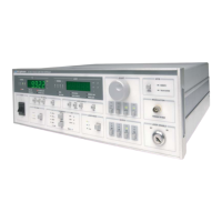
LDC-3900 Front Panel
10_15 LDC-3900 Series 29
CHAPTER 2
Laser Parameter Set
The (Parameter) Set switch is used to enter Set mode, where parameter values
may be edited and are then stored into non-volatile memory.
If the (Parameter) Set switch is pressed while the unit is in Select mode, the unit
will enter Set mode. While the (Parameter) Set switch is held in, the selected
parameter value can be change by rotating the Adjust Knob. The new value is
stored in non-volatile memory when the (Parameter) Set switch is released.
LIM I
The LIM I parameter is used to set the absolute upper limit for Laser output
current. During operation, when the Laser current limit is reached, the CURRENT
LIMIT Error Indicator flashes.
If the optional GPIB is implemented, the Laser current limit condition may be used
to turn the Laser output off via the LASer:ENABle:OUTOFF command.
The LIM I Indicator becomes lit when the low range laser current limit is displayed.
The current limit setting is independent of the voltage drop of the device
connected to the Laser output, and therefore, no dummy load is required for
precise adjustment of the current limit. Furthermore, since the current limit
circuitry is fully independent of the main current control, the current limit can be
adjusted safely, even while the Laser output is active.
LIM P
The LIM P is the absolute limit of optical power, as detected by the unit via the
monitor PD feedback scheme. In order for this limit to be meaningful, the monitor
photodiode responsivity (CAL PD) must be adjusted correctly. (See CAL PD on
page 29.)
This limit is a software limit only. The Laser output is normally turned off if this limit
is reached (unless this condition to turn the Laser output off is disabled via the
remote LASer:ENABle:OUTOFF command). The maximum LIM P value depends
on the laser module type. Refer to the Laser module instruction manual.
During operation, when the Laser power limit is reached, the POWER LIMIT Error
Indicator flashes.
CAL PD
The CAL PD Indicator becomes lit when the monitor photodiode responsivity
parameter is displayed. The responsivity is displayed in A/mW. The responsivity
is entered by the user (in A/mW) after performing the following measurements:
• Measure (with a calibrated detector) the output power of the device.
• Measure the corresponding photodiode current.

 Loading...