8
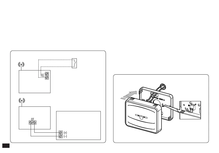
Telephone control
(optional)
CHRONO RF
BASE RF
BOILER
3) To make the electrical connections (Fig. 1-4) do not
operate when the boiler is live. e connection must
be made to the relative clamps and the jumper on
clamps 40 and 41 of the boiler P.C.B. (if present) must
be eliminated.
en connect the base to the boiler clamps envisioned
during communication with the CAR
V2
or, if not
present, to the clamps envisioned for the CRD
indicated as 40 and 41 or 41 and 44.
Note: refer to the electrical connections stated in the
boiler instruction book.
Important: do not connect to clamps 42 and 43.
e connection to the boiler is made using two wires (Fig.
1-5) with a minimum section of 0.50 mm
2
and maximum
1.5 mm
2
and with a maximum length of 50 metres.
Fig. 1-4
Fig. 1-5