9
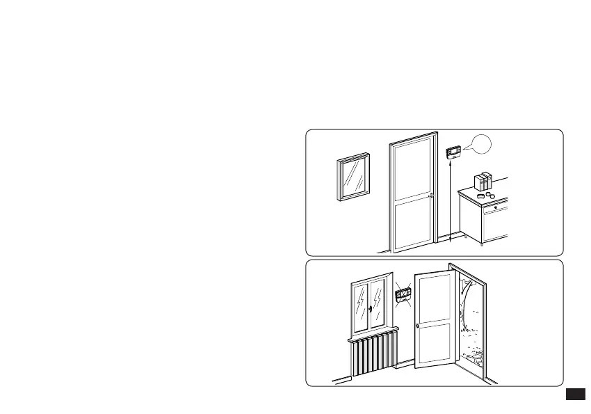
Fig. 1-7
Fig. 1-6
OK
1,5m
NO
N.B: for correct installation prepare a dedicated line for
the connection of the Base according to the Standards in
force regarding electrical systems. If this is not possible,
interference due to other electric cables could cause the
Base to malfunction.
4) Fasten the lid of the CAR
V2
Base to the support bottom,
engaging it using pressure (Fig. 1-5).
N.B.: when closing the lid, make sure it is aligned correctly
with the bottom.
6) Separate the xing template from the body of the CAR
V2
using a screwdriver as a lever in the relative recess (Fig.
1-8). Install the CAR
V2
away from heat sources and in a
suitable position to detect the room temperature correctly
(Fig. 1-6 and 1-7).
7) Install the CAR
V2
using the openings on its rear part
directly onto the wall or on a recess box using the relative
supplied screws.
8) Fasten the body of the CAR
V2
to the support template,
engaging it with pressure and using the two screws
supplied (Fig. 1-8).
9) Insert 2 1.5 V AA batteries (not supplied) into the pre-set
housing (Fig. 1-8) and close the battery compartment.
10) e Base and the CAR
V2
are associated to each other
during the testing phase in the factory. erefore, an
additional radio frequency association procedure is not
necessary.
1.5 m