Extensions for horizontal kit. e horizontal in take/
exhaust kit Ø 80/125 can be extended up to a
horizontal length of 7300 mm
including the terminal grille
and excluding the concentric bend on output of the boiler
and the adapter Ø 60/100 in Ø 80/125 (see gure). is
con guration cor re sponds to a resistance factor of 100. In
these cas es spe ci c extensions must be requested.
when installing the ducts, a section clamp with pin
must be installed every 3 metres.
for safety purposes, do not totally or
partially obstruct the boiler intake/exhaust terminal even
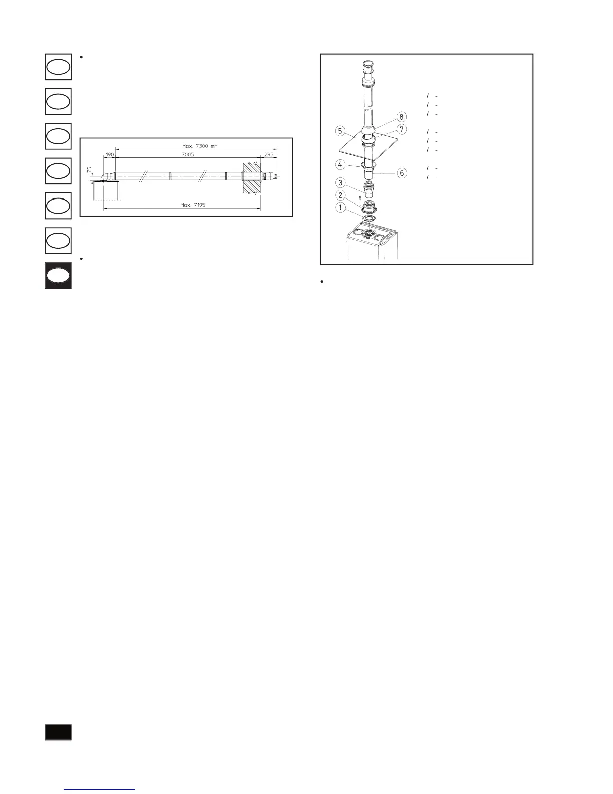
Vertical kit with aluminium tile Ø 80/125.
install the concentric ange (2) on the cen tral hole of the
boiler taking care to insert the seal (1) supplied with the kit
and tighten by means of the screws supplied with the boiler.
Fit the male section (smooth) of the adapter (3) coin the
female section of the concentric ange (2). Installing the
imitation alu min i um tile. Replace the tile with the alumi-
nium sheet (5), shaping it to ensure o - ow of rainwater.
Position the xed half-shell (7) on the aluminium tile and
insert the intake/exhaust pipe (6). Fit the con cen tric ter mi nal
Ø 80/125 with the male section (6) (smooth), in the female
section of the adapter (3) (with lip seal) to the end stop,
ensuring that washer (4) si already t ted to ensure sealing
e ciency of all cou plings.
Snap t extension pipe ttings and concentric elbows Ø
80/125. To install snap- t ex ten sions with other elements
of the boiler assembly, pro ceed as follows: t the concentric
pipe or elbow with the male section (smooth) on the female
sec tion (with lip seal) to the end stop on the previously
installed to ensure sealing e ciency of the cou plings.
if the exhaust terminal and/or extension concen-
tric pipe needs shortening, consider that the internal duct
must always protrude by 5 mm with re spect to the external
is speci c terminal enables ue exhaust and air intake in
the vertical kit Ø 80/125 with aluminium tile en a bles
installation on terraces and roofs with max i mum gradient
of 45% (24°) and the height between the ter mi nal cap and
half-shell (374 mm) must be strictly observed.
is vertical kit con guration can be extended to a
in a vertical straight route, including
the terminal (see gure next page). is con g u ra tion cor-
responds to a resistance factor of 100. In this case speci c
extensions must be re quest ed.
Terminal Ø 60/100 can also be used for vertical ex haust,
in conjunction with concentric ange code no. 3.011141
(sold separately). height between the ter mi nal cap and half-
shell (374 mm) must be strictly ob served (see drawing next
is vertical kit con guration can be extended to a
in a vertical straight line, including the
terminal (see gure next page).
Female concentric ange (2)
Int./exh. concentric pipe Ø