seal) to the end stop on the previously installed to ensure
sealing e cien cy of the couplings.
Insulation of separator terminal. In the event of prob lems
of condensation of ues inside the ex haust pipes or on the
outside surface of the intake pipes, on request Immergas
supplies insulated in take and exhaust pipes. Insulation
may be nec es sary on exhaust pipes due to excessive drops
in tem per a ture of ues during conveyance from the boiler
and on the intake pipes as air on input (cold) may cause
the external pipe temperature lower than the dew point
of the ambient air. e gures below il lus trate di erent
applications of insulated pipes.
Insulated pipes comprise an internal Ø 80 con cen tric pipe
and a Ø 125 external pipe with static air jacket. Technically
it is not possible to start with both Ø 80 elbows insula-
ted as clearances will not allow this type of installation.
However an in su lat ed el bow can be used by selecting either
the intake or exhaust pipe. If an insulated intake pipe is
used, the ange must be inserted to the end stop on the
ue extraction ange to ensure that the height of the two
intake and exhaust outlets is aligned.
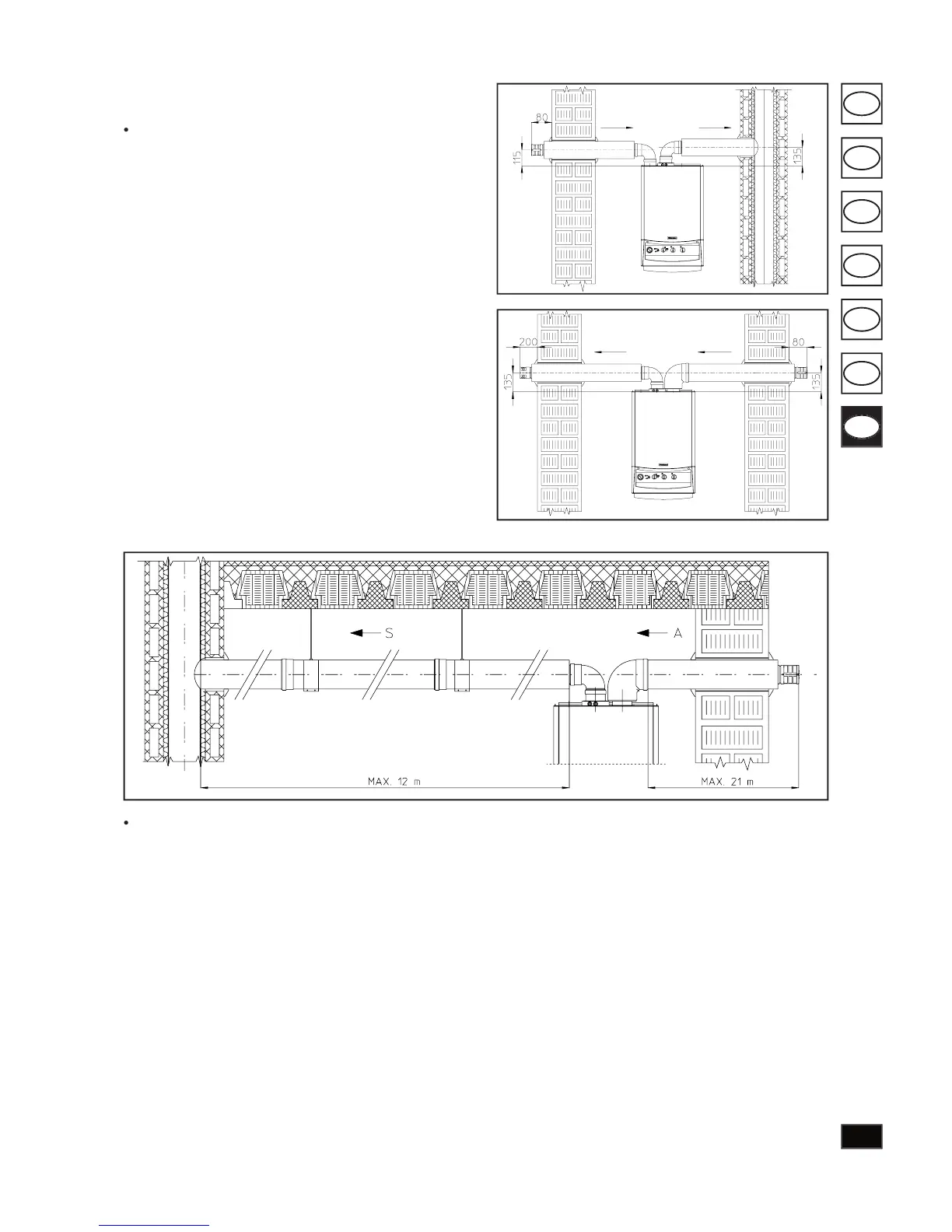
Temperature loss in insulated ducting. To avoid the pro-
blem of ue condensation in insulated exhaust Ø 80
pipes, due to cooling via the wall,
must be restricted to 12 me tres.
e gure above illustrates
a typical in su la tion ap pli ca tion in which the intake pipe is
short and the ex haust pipe very long (over 5 m). e entire
in take pipe is insulated to prevent condensation of humid
air in the boiler environment in contact with the cooled
pipe conveying cool outdoor air. e entire exhaust pipe
is insulated with the ex cep tion of the elbow on output of
the splitter, to reduce heat dis per sion from the duct and
prevent for ma tion of ue condensate.
when installing the insulated ducts, a sec tion clamp
with pin must be installed every 2 me tres.
Flue exhaust does not necessarily have to be con nect ed a
branched type traditional ue and can be connected to a
special LAS type multiple ue. Flues must be specially desi-
gned according to spec i ca tions in the standard by quali ed
pro fes sion al personnel.
Chimney or ue sections for connection of the ex haust pipe
must comply with requirements as laid down in standards.
With a speci c “ducting system” it is possible to re use existing
ues, chimneys and technical slots to discharge the boiler
fumes. Ducting requires the use of ducts declared suitable for
the purpose by the manufacturer, following the installation
and op er a tion instructions provided by the manufacturer,
and the requirements standard.