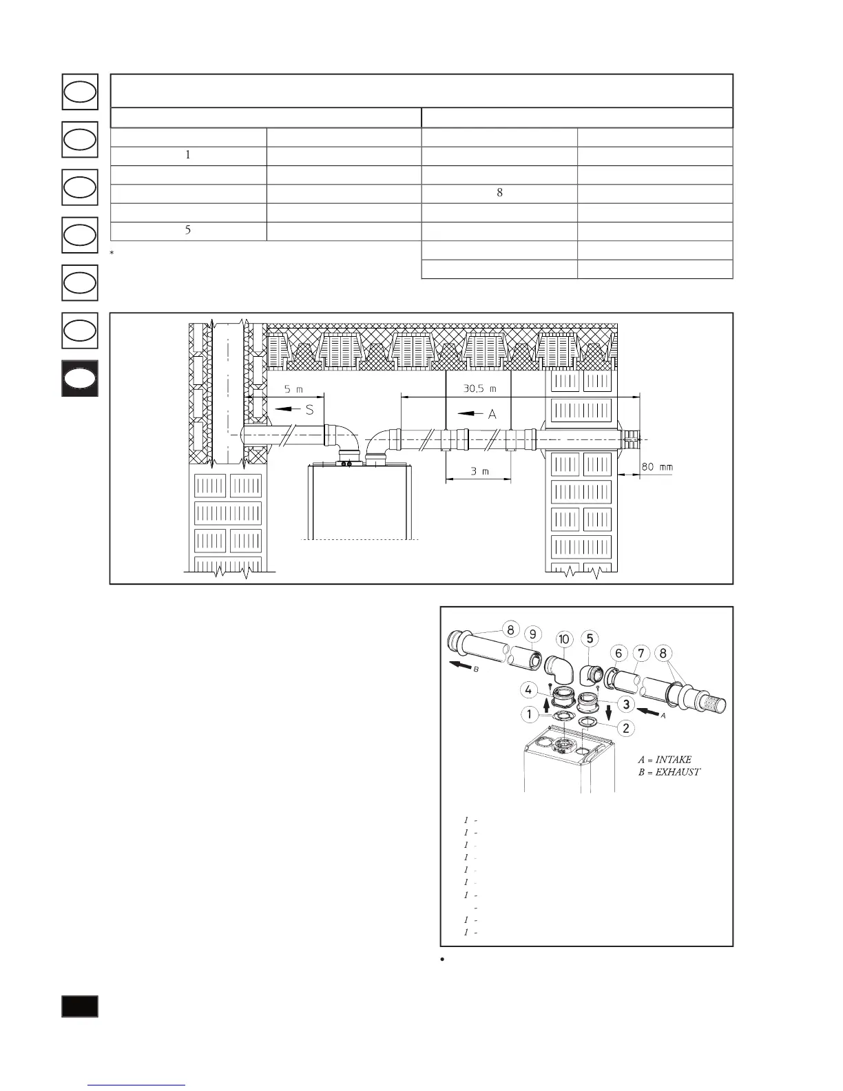
when installing the Ø 80 ducts, a section clamp with
pin must be installed every 3 metres.
Insulated separator kit Ø 80/80.
Kit assembly: In stall ange
(4) on the central hole of the boiler tak ing care to insert
seal (1) supplied with the kit and tighten by means of the
screws on the boiler. Re move the at ange on the lateral
hole (de pend ing on in stal la tion requirements) and replace
with ange (3) in sert ing seal (2) already tted on the boil er
and tighten with the screws supplied. Insert and slide cap (6)
onto bend (5) on the male sec tion (smooth) and join bends
(5) with the male section (smooth in the female section of
ange (3). Fit bend (10) with the male section (smooth) in
the female sec tion of ange (4). Join the intake terminal (7)
with the male section (smooth in the female sec tion of bend
(5) to the end stop, ensuring that wash ers (8) are in sert ed to
achieve correct installation between the pipe and wall and
t the end cap (6) on terminal (7). Join the exhaust pipe
(9) with the male section (smooth) in the female section of
the bend (10) to the end stop, ensuring that the washer (8)
is already inserted for correct installation between the pipe
Snap t extension pipe ttings and elbows. To in stall snap-
t extensions with other elements of the boiler assembly,
proceed as follows: t the con cen tric pipe or elbow with
the male section (smooth) on the female section (with lip
Maximum e ective lengths
(including intake terminal with grille and two 90° bends)
e intake duct can be increased by 2.5 metres if the bend on
exhaust is eliminated, 2 metres if the intake bend is eliminated
or 4 metres of both bends are removed.
Female exhaust ange (4)
Insulated intake terminal Ø 80 (7)
Insulated exhaust pipe Ø 80 (9)
Concentric 90° bend Ø 80/125 (10)