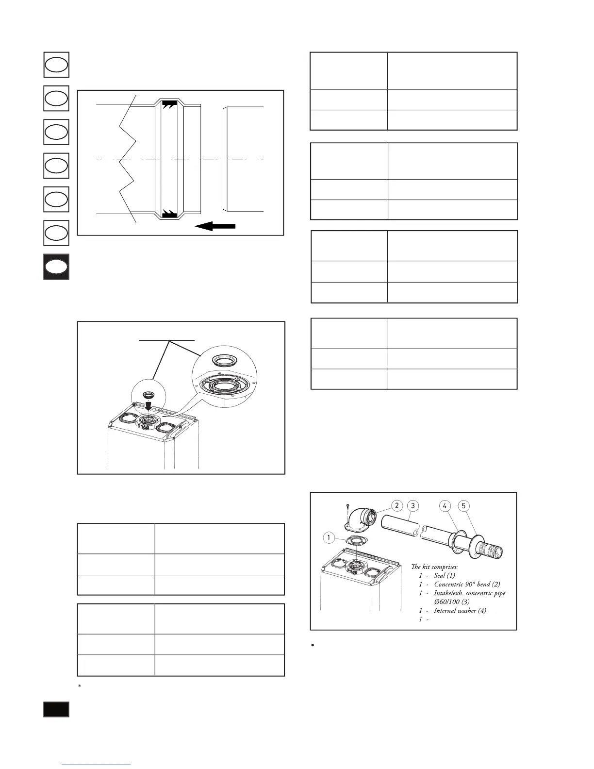
Horizontal intake-exhaust kit Ø60/100.
install the bend with ange (2) on the central hole of the
boiler taking care to insert the seal (1) and secure by means of
the screws supplied with the kit. Join the male end (smooth
section) of ter mi nal pipe (3) to the female section (with lip-
seal) of bend (2) to the end stop and ensure that the in ter nal
and ex ter nal washers are tted to achieve per fect seal ing of
Snap- t couplings of concentric pipes or ex ten sions and
elbow ttings Ø60/100. To install extension cou plings
on other ue extraction components, pro ceed as follows:
t the concentric pipe or con cen tric elbow with the male
section (smooth) on the female section (with lip-seal) of
the previously in stalled component to the end stop to
ensure per fect sealing of the coupling.
To ensure correct op er a tion of the
boiler, a diaphragm (see gure) must be in stalled on output
of the sealed chamber before the intake and exhaust duct.
Selection of a suitable di a phragm depends on the type of
ducting used and maximum length: calculations can be made
using the values in the tables below:
Diaphragms are supplied as standard with the boi-
e values for maximum length are considered with 1 metre
of exhaust pipe and the remaining on in take.
Ø 80 horizontal duct with two bends
Ø 80 vertical duct without bends
Positioning of double-lip seals.
For correct po si tion ing of
the lip seals on elbows and extensions, follow the order of
assembly shown in the gure.
Intake/exh. concentric pipe