To start up the boiler, proceed as follows:
ensure that the declaration of conformity of in stal la tion is
supplied with the appliance;
ensure sealing e ciency of the gas intake circuit with the
shuto valves closed and then with the valves open and
the gas valve deactivated (closed); the meter must not
indicate gas transfer for at least ten minutes;
ensure that the gas used corresponds to spec i ca tions for
ensure connection to a 230V-50Hz power mains, correct
L-N polarity and the earthing connection;
switch on the boiler and ensure correct ignition;
ensure that the maximum, intermediate and min i mum gas
ow rate and relative pressure val ues conform to speci ca-
tions in the booklet on page 122;
ensure activation of the safety device in the event of gas
supply failure, as well as the relative ac ti va tion time;
ensure activation of the main switch downstream of the
boiler and inside the boiler;
check that the intake and/or exhaust terminals are not
ensure activation of the safety pressure switch in the event
ensure activation of all regulation devices;
seal the gas ow rate regulation devices (if set tings are
ensure production of hot domestic water;
ensure sealing e ciency of water circuits;
ensure adequate ventilation and/or aeration of the boiler
If any checks/inspection give negative results, do not start
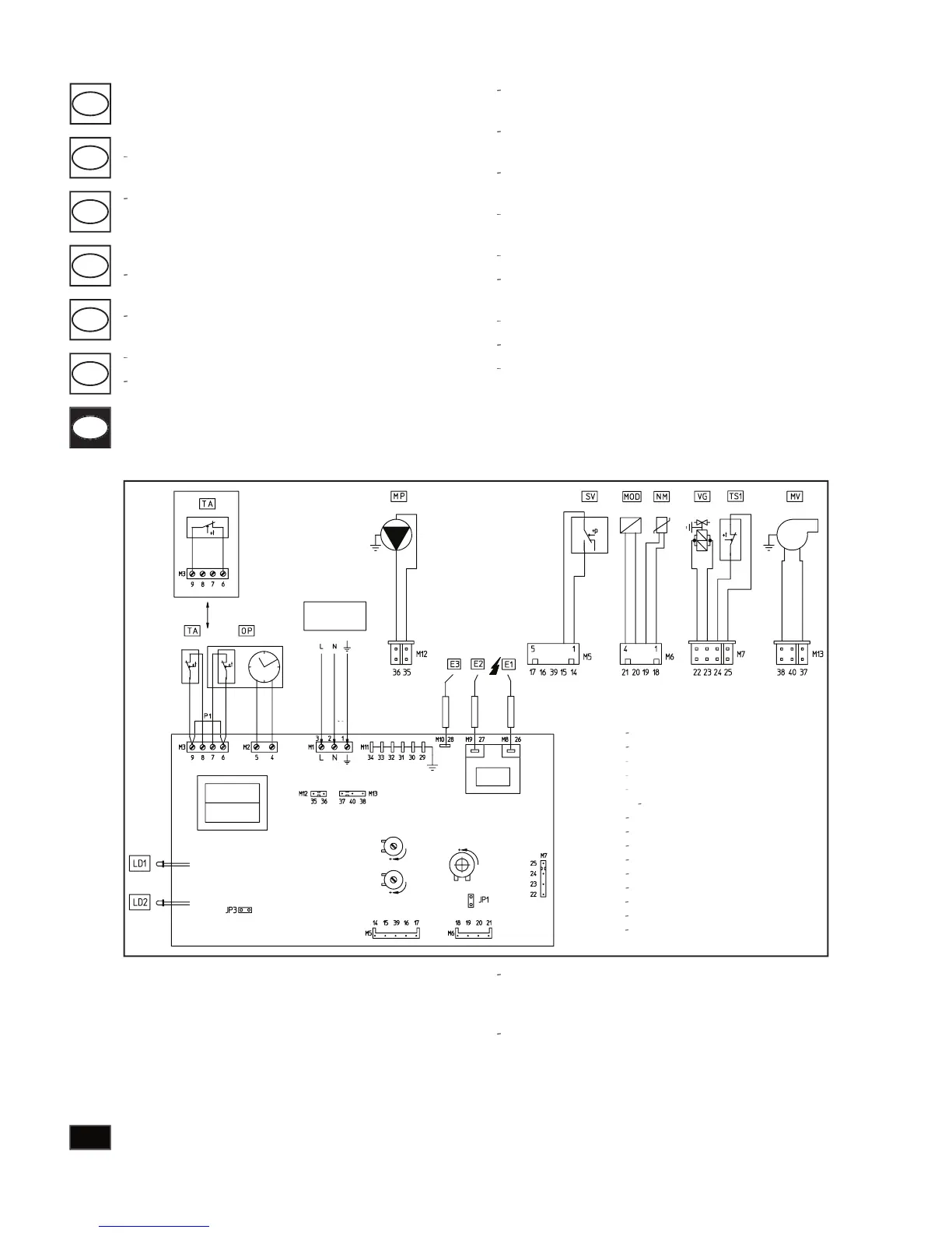
Room thermostat and clock programmer: the boiler is
designed for ap pli ca tion of an room thermostat (TA) and
of a clock programmer (CP). If you have only one of these
devices, connect to ter mi nals 6 and 9 and remove jumper P1.
Whereas if you have both, connect (TA) on terminals 8 and
9, and (CP) on terminals 6 and 7, after removing P1.
Electronic card function options.
e electronic card is equipped with jumpers de signed to
regulate boiler operation according to spe ci c in stal la tion
Eolo Mini S electrical circuit diagram.
Jumper JP1: when inserted the appliance op er ates with
LPG; when removed the appliance operates with natural
JP3 jumper; when inserted, after the heating tem per a ture
is reached the boiler only re-starts after 3 minutes; when
removed, the interval before re-start changes to 30 seconds,
useful for convection fan systems.
Room thermostat On/O (optional)
Temp. overload safety thermostat