Sensor fault - Yellow indicator lamp (2) ashing.
tion, if the control unit detects a fault on the NTC sensor, the
boiler does not start; in this case contact a quali ed technician
for assistance (e.g. Immergas Technical Services Centre).
Turn o the main switch (4) by setting
to “0” (yellow indicator lamp 2 OFF) and close the gas sup-
ply valve upstream of the appliance. Nev er leave the boiler
switched on if left unused for pro longed periods.
Periodically check the system water pressure. e boiler pres-
sure gauge should read a pressure be tween 1 and 1,2 bar.
If the pressure falls below 1 bar (with the circuit cool) restore
normal pressure via the valve located at the bottom of the boiler
close the valve on completion.
If pressure values reach around 3 bar the safety valve may
In this case contact a professional technician for as sist ance.
In the event of frequent pressure drops, contact qual i ed
personnel for assistance to eliminate system leak age.
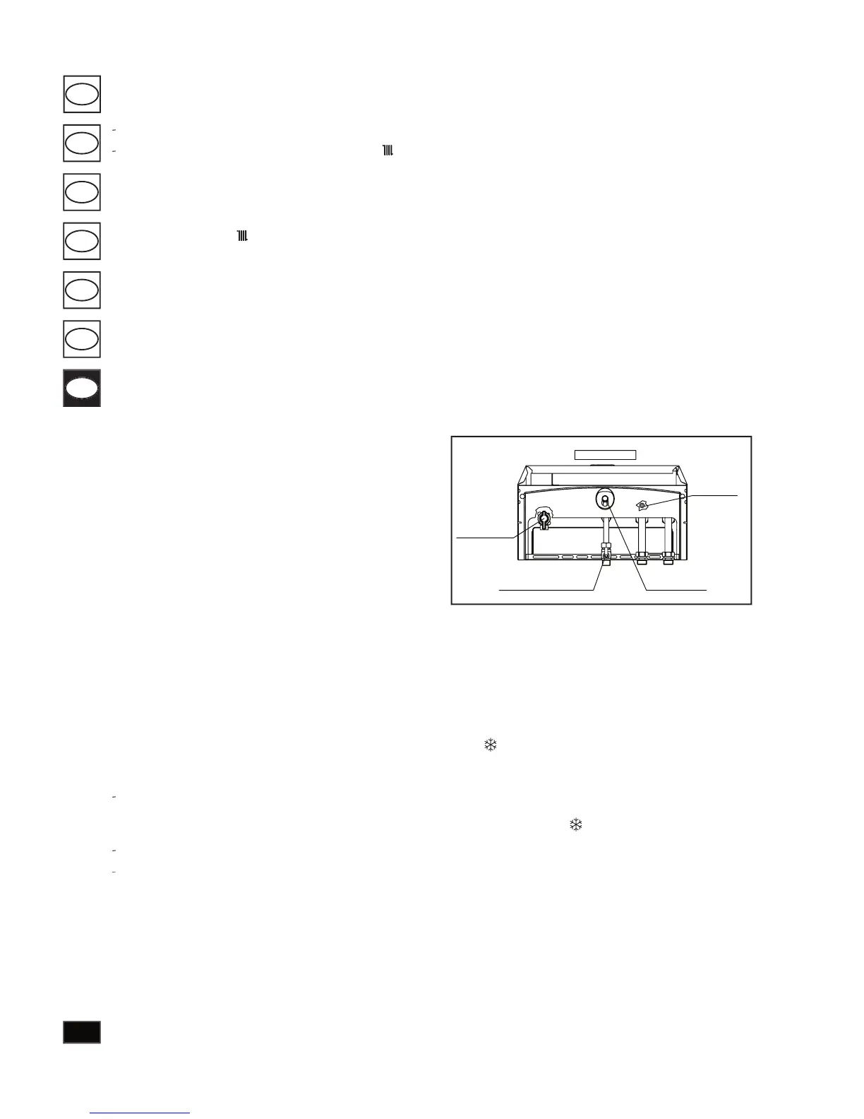
To drain the system completely, use the drain valve (see gure
Before draining, ensure that the lling valve is closed.
e boiler is equipped as standard with an anti-freeze fun-
) that activates the pump and burner when sys tem
water temperature falls below 8°C and de ac ti vates once
temperatures reach 43°C. e anti-freeze function is gua-
ranteed if the boiler is totally operative and not in “block”
status, when connected to the elec tri cal power supply and
) mode. To avoid continued ope-
ration in the event of prolonged absence, the sys tem must
be drained completely or anti-freeze sub stanc es should be
added to the heating system wa ter. In appliances subject to
fre quent draining, the system must be re lled with suit a bly
treated water to elim i nate hardness that may cause limescale
Before switching on the boiler, check that
the system is lled with water and that gauge (1) indicates
Open the gas valve downstream of the boiler.
Turn the main switch (4) to the setting Heating (
enable standby mode, i.e. boil er on but no ame present
(both indicator lamps switched o ), this status remains
until the burner is ignited and the cir cu la tion pump is
activated (indicator lamp 2 ON).
) the heating regulation se lec tor
(5) is used to regulate the temperature of ra di a tors, rotate
clockwise to increase the temperature and counterclockwise
Boiler operation is now automatic.
Ignition block - Red indicator lamp (3) ON.
heating is required the boiler is activated automatically. If
this does not oc cur within 10 seconds, the boiler activates
an “ig ni tion block” (indicator lamp 3 ON). To eliminate the
block, rotate the main switch (4) temporarily to the Reset
position. On initial ignition or following a pro longed period
of disuse the ignition block may need to be inhibited. If this
function is activated re peat ed ly, con tact a quali ed technician
for assistance (e.g. Immergas Technical Services Centre).
Temperature overload block – Red indicator lamp (3)
During normal operation, if a fault causes a in-
ternal tem per a ture overload condition, boiler operation is
To startup the boiler, set the main switch (4) tem po rar i ly
to Reset. If this fault occurs repeatedly, contact a quali ed
technician for assistance (e.g. Immergas Technical Services
Air pressure switch activation failure - Red in di ca tor
lamp (3) and yellow indicator lamp (2) ash ing.
condition occurs if the intake or ex haust pipes are blocked
or a fan fault. In this case contact a quali ed technician
for assistance (e.g. Immergas Technical Services Centre). If
normal con di tions are restored the boiler resumes operation
with out requiring reset.
Insu cient circulation water – Red indicator lamp (3)
ON, yellow indicator lamp (2) ash ing.
the boiler is overheating because of insu cient circulation of
water in the primary circuit; causes may be the following:
low circulation system; check that no shuto devices are
closed on the heating circuit or that any air bub bles are
circulator blocked; release (see page 113).
the water pressure in the heating circuit is not enough to
guarantee the correct functioning of the boiler. Check that
pres sure is between 1 and 1,2 bar;
If normal con di tions are restored the boiler resumes operation
with out requiring reset.
If this function is activated re peat ed ly, con tact a quali ed
technician for assistance (e.g. Immergas Technical Services
Bottom view
Gas cock
Filler cock
Drain cock
Domestic water inlet cock