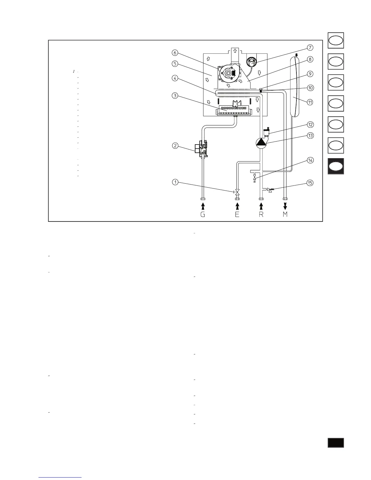
Eolo Mini S hydraulic circuit diagram.
maintenance must be performed by quali ed person-
nel (e.g. Immergas Technical Service Cen tre).
Smell of gas. Caused by leakage from gas circuit pipelines.
Check sealing e ciency of gas intake cir cuit.
e fan works but the discharge of ignition on the burner
ramp is not activated. e fan may start but the safety air
pressure switch does not change the contact. In the case
that the intake-exhaust duct is not too long (over ad-
that the intake-exhaust duct is not partially blocked (on
either the exhaust or intake side).
that the diaphragm on the ue exhaust outlet is com-
mensurate with the length of the intake/ex haust duc-
that the sealed chamber is perfectly sealed.
that the fan power supply voltage is minimum 196 V.
Irregular combustion (red or yellow ame). is may be
caused by a dirty burner, blocked reed valve, or incorrect
installation of the intake-ex haust ter mi nal. Clean the spe-
ci ed components and en sure cor rect installation of the
Frequent activation of the temperature overload ther mo -
stat. is may be caused by lack of water in the boiler.
insu cient water circulation in the cir cuit or a blocked
circulator. Check via the pressure gauge that values are
within admissible limits. Check that radiator valves are
not all closed and that the cir cu la tor operates correctly.
Presence of air in the system. Ensure opening of the hood
on the air venting valve (see g. page 114). Ensure that
system pressure and pre-charge of the expansion vessel are
within the set limits; the per-charge value for the expansion
vessel must be 1 bar, and system pressure between 1 and
Ignition block; see pages 116 and 102 (electrical con nec -
Converting the boiler to other types of gas.
In the event of converting the boiler for a gas type oth er than
that speci ed on the dataplate the rel a tive con ver sion kit must
be requested for quick and easy con ver sion.
Conversion of the boiler must be performed by a skilled
technician (e.g. Immergas Technical Serv ic es Cen tre).
To convert to another type of gas the following op er a tions
main burner nozzle replacement;
movement of jumper (13 page 121) to correct po si tion for
type of gas required (Natural or LPG);
adjustment of minimum boiler heating power;-
adjustment of maximum boiler heating power;
adjustment of heating power;
adjustment of rst slow step of burner ig ni tion;
sealing of gas ow rate devices (if modi ed);
when transformed the boiler, append the adhesive con-
tained into transformation kit, near data-sheet of boiler.
On the data-sheet is necessary to cancel (using an indelible
marker) data of old type of gas.
Fan safety pressure switch
Temp. overload safety thermostat
NTC limit and regulation sensor
Automatic air venting valve