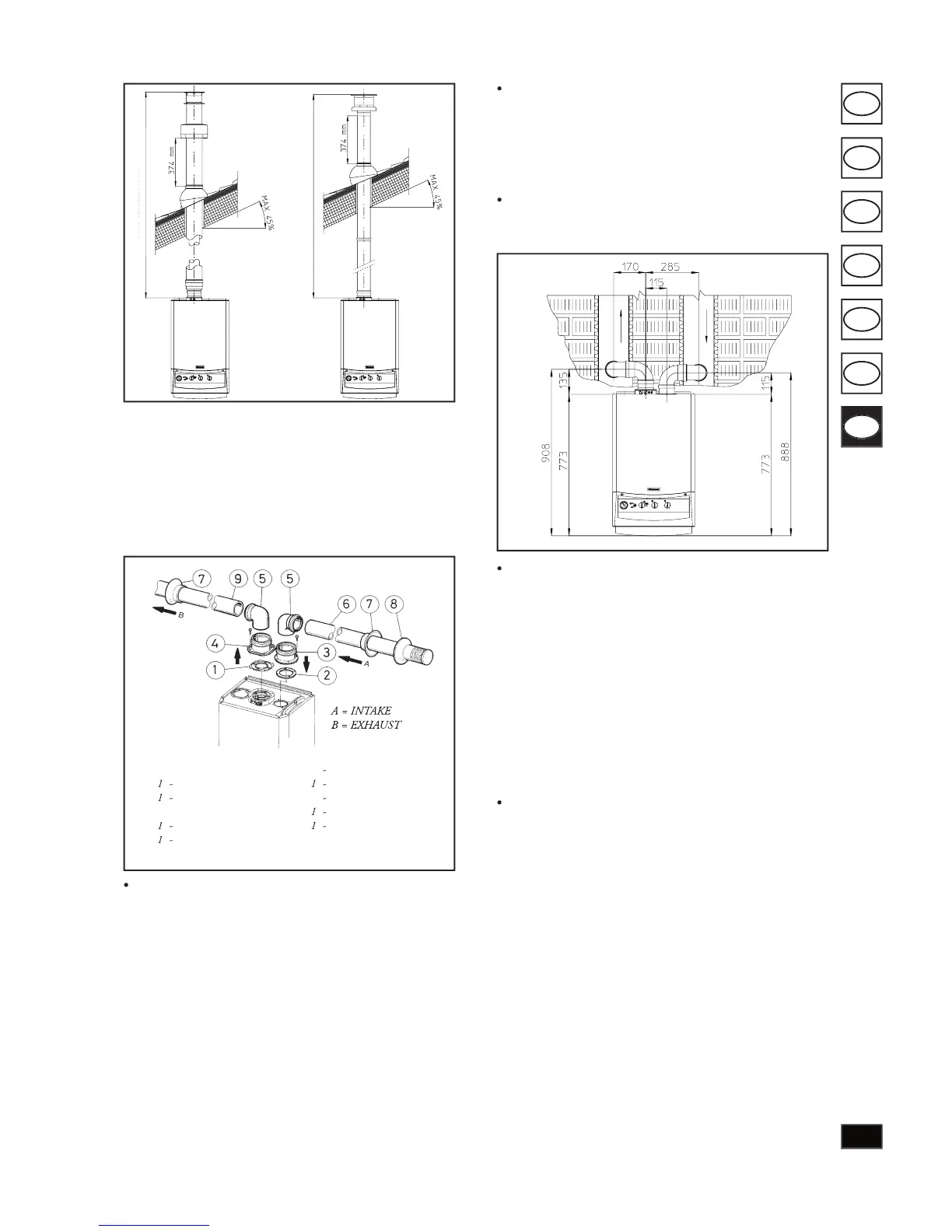
e separator kit Ø 80/80, enables
the division of the ue exhaust pipes and air intake pipes
according to the diagram shown in the gure. Combustion
products are expelled from duct (B). Air is taken in through
duct (A) for combustion. Intake duct (A) can be installed
either on the right or left hand side of the central exhaust
duct (B). Both ducts can be routed in any direction.
Assembly of separator kit Ø 80/80. Install ange (4) on
the central hole of the boiler taking care to insert seal (1)
supplied with the kit and tighten by means of the screws
on the boiler. Remove the at ange on the lateral hole
(depending on in stal la tion requirements) and replace with
ange (3) inserting seal (2) already tted on the boiler and
tighten with the screws supplied. Joins bends (5) with the
male section (smooth) in the female section of the anges
(3 and 4). Fit the intake terminal (6) with the male section
(smooth) in the female section of the ange (5) to the end
stop with the internal and external washers in sert ed. Join
the exhaust pipe (9) with the male sec tion (smooth) in the
female section of the bend (5) to the end stop ensuring
that the internal washer is tted and to ensure sealing
e ciency of the cou plings.
Snap t extension pipe ttings and elbows. To in stall snap-
t extensions with other elements of the boiler assembly,
proceed as follows: t the pipe or elbow with the male
section (smooth) on the fe male section (with lip seal) to
the end stop on the previously installed to ensure sealing
e ciency of the couplings.
Installation clearances. e following gure shows the mi-
nimum installation clearances for the ter mi nal separator
kit Ø 80/80 in maximum admissible conditions.
Extensions for separator kit Ø 80/80. e max i mum
straight length (without bends) on a vertical route, for
intake and exhaust pipes Ø80 is 41 me tres, 40 of which
on intake and 1 on exhaust. is total length corresponds
to a re sist ance factor of 100. e total e ective length,
obtained by adding the length of intake and exhaust pipes
Ø 80 must not exceed the maximum values speci ed in
mixed accessories or components
(e.g. changing from a separator Ø 80/80 to a con cen tric
pipe), the maximum extension can be cal cu lat ed by using
the resistance factor for each component or the
. e total of the resistance factors must not exceed
Temperature drops in ue ducts. To avoid the prob lem of
ue condensation in the exhaust pipe Ø 80, due to cooling
If longer distances have to be covered,
use pipe diameters Ø 80 with insulation (see insulated