C
82
C
52
C
42
C
82
23
24
25 26
4
6
5
1
3
2
7
8
5
9
7
A
S
22
INSTALLER
USER
MAINTENANCE TECHNICIAN
TECHNICAL DATA
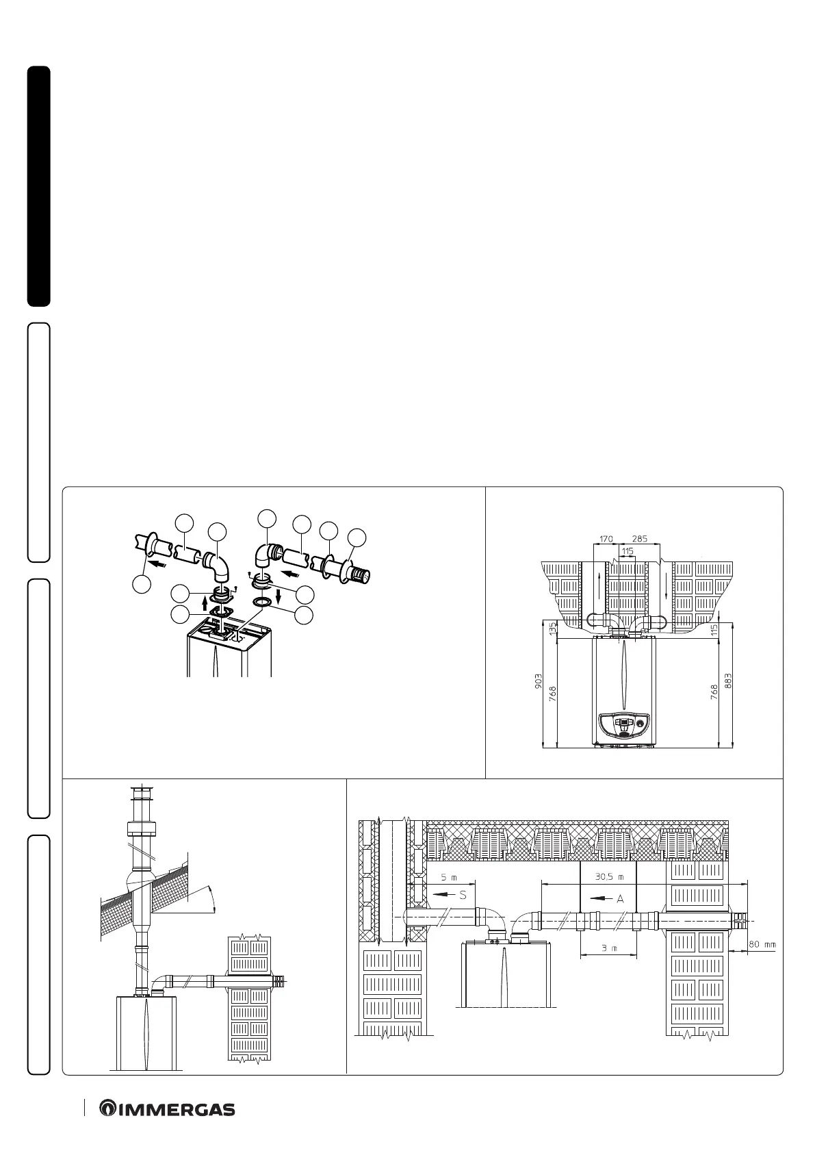
• Separator kit Ø 80/80.
e Ø 80/80 separator kit, allows separation of the exhaust ues
and air intake pipes according to the diagram shown in the gure.
Combustion products are expelled from pipe (S). Air is taken
in through pipe (A) for combustion. e intake pipe (A) can be
installed either on the right or le hand side of the central exhaust
pipe (S). Both ducts can be routed in any direction.
Please note the type of installation C
4
must be done with a nat-
ural draught ue. Moreover, with C
5
conguration, intake and
exhaust pipes cannot be installed on opposing walls.
• Kit assembly (Fig. 23): install ange (4) on the central hole of
the boiler, tting gasket (1) and tighten with the at-tipped
hex screws included in the kit. Remove the at ange present
in the lateral hole with respect to the central one (according to
needs) and replace it with the ange (3), positioning the gasket
(2) already present in the boiler and tighten using the supplied
self-threading screws. Fit the male end (smooth) to the bends (5)
in the female end of the anges (3 and 4). Fit the intake terminal
(6) with the male section (smooth) in the female section of the
bend (5) up to the stop, ensuring that the internal and external
wall sealing plates are tted. Fit the exhaust pipe (9) with the male
end (smooth) to the female end of the bend (5) up to the stop;
making sure that the internal wall sealing plate has been tted.
is will ensure sealing and joining of the elements making up
the kit.
• Coupling of extension pipes and elbows. To install push-tting
extensions with other elements of the ue extraction elements
assembly, proceed as follows: engage the pipe or elbow with the
male side (smooth) in the female section (with lip seal) up to the
stop on the previously installed element. is will ensure sealing
eciency of the coupling.
• Installation clearances. Figure 24 gives the min. installation space
dimensions of the Ø80/80 separator terminal kit in limited
conditions.
• Figure 25 shows the conguration with vertical exhaust and
horizontal intake.
e kit includes:
N°1 - Exhaust gasket (1)
N°1 - Female intake ange (3)
N°1 - Flange seal (2)
N°1 - Female exhaust ange (4)
N°2 - 90° bend Ø 80 (5)
N°1 - Intake terminal Ø 80 (6)
N°2 - Internal wall sealing plates (7)
N°1 - External wall sealing plate (8)
N°1 - Exhaust pipe Ø 80 (9)
Max. 45%
* Conguration C
4
envisages connection to ues
working with natural draught.
** e conguration on walls
opposite the building is not allowed.