23
INSTALLER
USER
MAINTENANCE TECHNICIAN
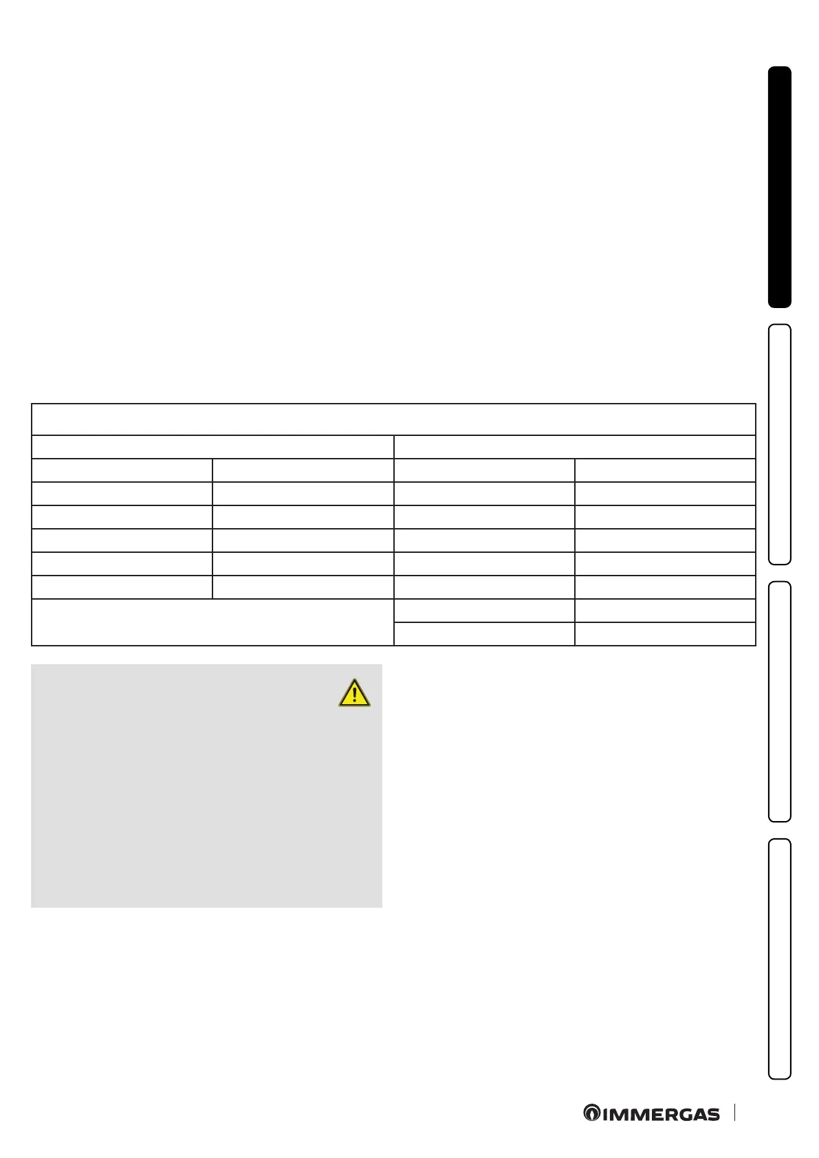
TECHNICAL DATA
Maximum usable length
(including intake terminal with grill and two 90° bends)
NON-INSULATED PIPE INSULATED PIPE
Drain (metres) Intake (metres) Drain (metres) Intake (metres)
1 36.0* 6 29.5*
2 34.5* 7 28.0*
3 33.0* 8 26.5*
4 32.0* 9 25.5*
5 30.5* 10 24.0*
* e air intake pipe can be increased to 2.5 metres if the exhaust bend
is eliminated, 2 metres if the air intake bend is eliminated, 4.5 metres
eliminating both bends.
11 22.5*
12 21.5*
ATTENTION:
if installation requires extending the
ue ttings up to the exhaust a length
that exceeds the 12 m recommended, it is
necessary to properly consider the possibility
that condensation may form inside the duct
and therefore Immergas “Serie Blu” insulated
ue ttings, or other ue ttings with similar
characteristics, should be used.
It’s not allowed that condensation ow towards
the appliance from exhaust ducts.
• Extensions for the separator kit Ø 80/80. e max. vertical
straight length (without bends) that can be used for Ø 80 intake
and exhaust pipes is 41 metres of which 40 intake and 1 exhaust.
e total length corresponds to a resistance factor of 100. e
total usable length obtained by adding the length of the intake
and exhaust pipes Ø 80, must not exceed the values stated in
the following table. If mixed accessories or components are used
(e.g. changing from a separator Ø 80/80 to a concentric pipe),
the maximum extension can be calculated by using a resistance
factor for each component or the equivalent length. e sum of
these resistance factors must not exceed 100.
• Temperature loss in ue ducts.
To prevent problems of fume condensate in the exhaust pipe Ø
80, due to fume cooling through the wall, the length of the pipe
must be limited to just 5 m. (Fig. 26). If longer distances must be
covered, use Ø 80 pipes with insulation (see insulated separator
kit Ø 80/80 chapter).
N.B.: when installing the Ø 80 ducts, a section clamp with pin
must be installed every 3 metres.