22
INSTALLERUSER
MAINTENANCE TECHNICIAN
4
1
2
3
56
7
8
9
10
1.8 CONNECTION WIRING
DIAGRAM SINGLE ZONE
HYDRONIC KIT SECOND
ZONE OPTIONAL AND
MAGIS COMBO PLUS
MAGIS COMBO PLUS V2
INTERNAL UNIT.
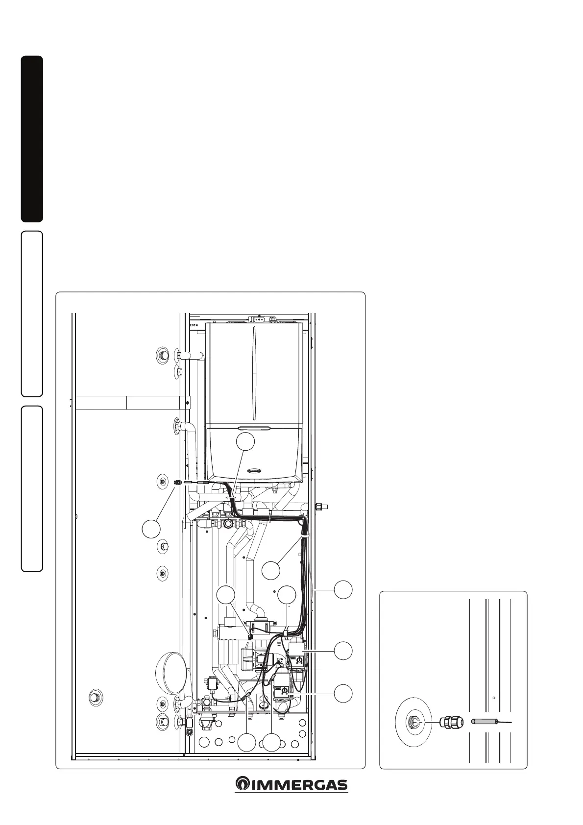
Once the kit is assembled, proceed with
the wiring according to the diagram
Fig. 26.
- Connect the cables in the Magis
Combo Plus - Magis Combo Plus V2
Internal Unit control panel following
the connection diagram in Fig. 32 - 33.
- Lower the wiring exiting the Magis
Combo Plus - Magis Combo Plus V2
Internal Unit until it can be secured
with the clips (1-2).
- Connect the storage tank probe
26
27
DHW probe - positioning (Det. 4)
terminals (4) to the device terminal
block / terminal board (see wiring
diagram Fig. 32 - 33) and position it
on the storage tank in the appropriate
seat (Fig. 27), using the relative cable
clamp.
- Connect the ow probe connector
(10) to the wiring marked by the label
“SONDA” (PROBE), then connect the
wiring to the probe and connect the
“T-SIC” connector to the safety ther-
mostat (Only if the second optional
zone is present).
- Connect the connector with the red
“M-Z1” label to the pump / circulator
(7) and connect the wiring terminals
to the device terminal block / termi-
nal board (see wiring diagram Fig.
32 - 33).
- Connect the connector with the green
“M-Z2” label to the pump / circulator
(8) (Only if the second optional zone
is present).
- Connect the connector of the mixing
valve (6) marked with the “V.MISC”
(MIX.V) label (Only if the second
optional zone is present).
- Connect the antifreeze box connector
(9) to the wiring connector with the
“ANTIFREEZE” label, and connect
the wiring terminals to the device
terminal block / terminal board (see
wiring diagram Fig. 32 - 33).
- Make the connection to the power
supply of the Internal Unit using
the cable (3) as shown in the wiring
diagram (Fig. 32 - 33)
- Now group the various cables and join
them with the clip (5) supplied with
the hydraulic manifold.
Attention: in order for the probes to
function properly, before it is insert-
ed, it is recommended to put a bit
of conductive paste on the relative
probe-holder.
N.B.: wind the uncovered ttings with
the insulation present in the kit.