37
INSTALLERUSER
MAINTENANCE TECHNICIAN
1
7
6
3
4
5
9
13
2
12
11
14
10
8
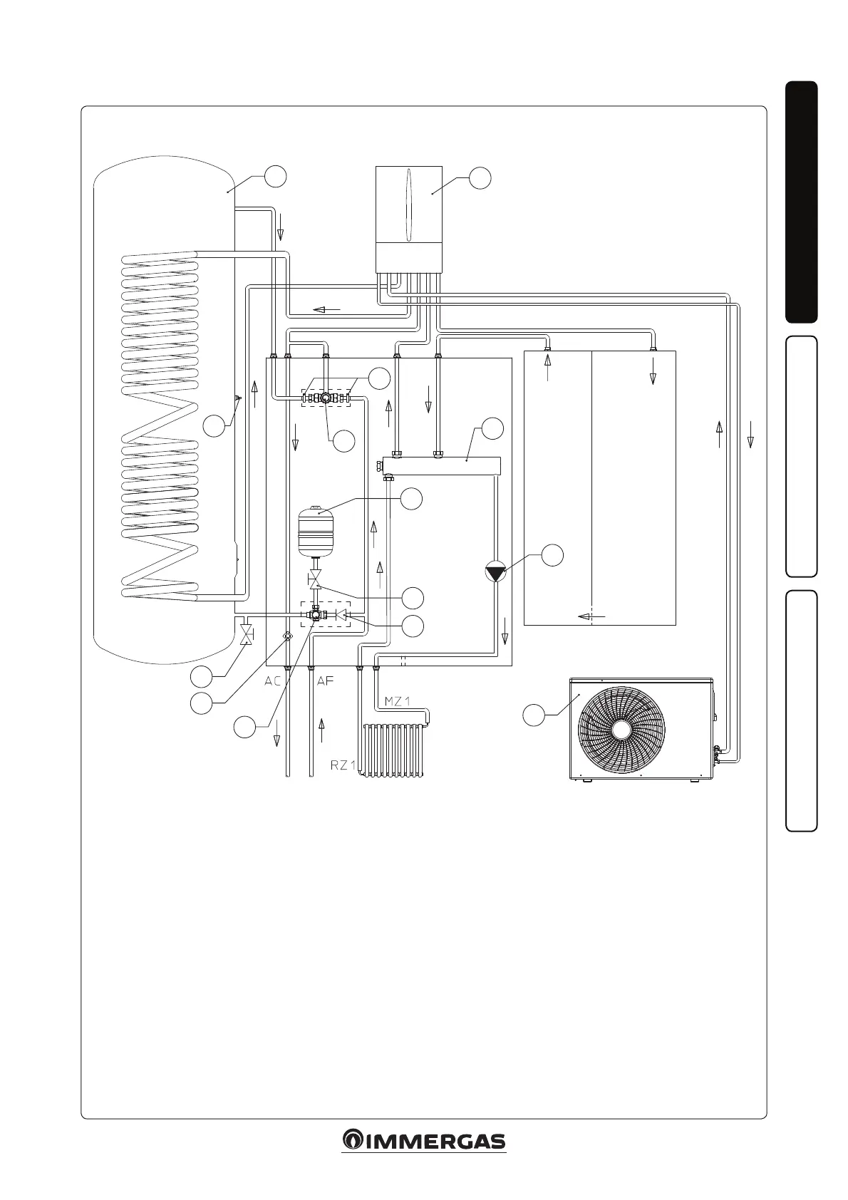
8 - DHW probe
9 - Direct zone pump
10 - One-way valve
11 - 8 bar safety valve
12 - Antifreeze thermostat
13 - Storage tank draining cock / tap
14 - Domestic hot water vessel shut-o
cock
AC - Domestic hot water outlet
AF - Domestic cold water inlet
MZ1 - High temperature system ow
RZ1 - High temperature system return
Key:
1 - Storage tank / Cylinder
2 - Condensing unit
3 - Hydraulic manifold
4 - 16 L DHW (Domestic hot water)
expansion vessel
5 - Magis Combo Plus
6 - Mixing valve lter
7 - DHW circuit mixing valve
1.23 HYDRAULIC DIAGRAM WITH MAGIS COMBO PLUS MAGIS COMBO PLUS V2 INTERNAL UNIT.
45