7
INSTALLERUSER
MAINTENANCE TECHNICIAN
3
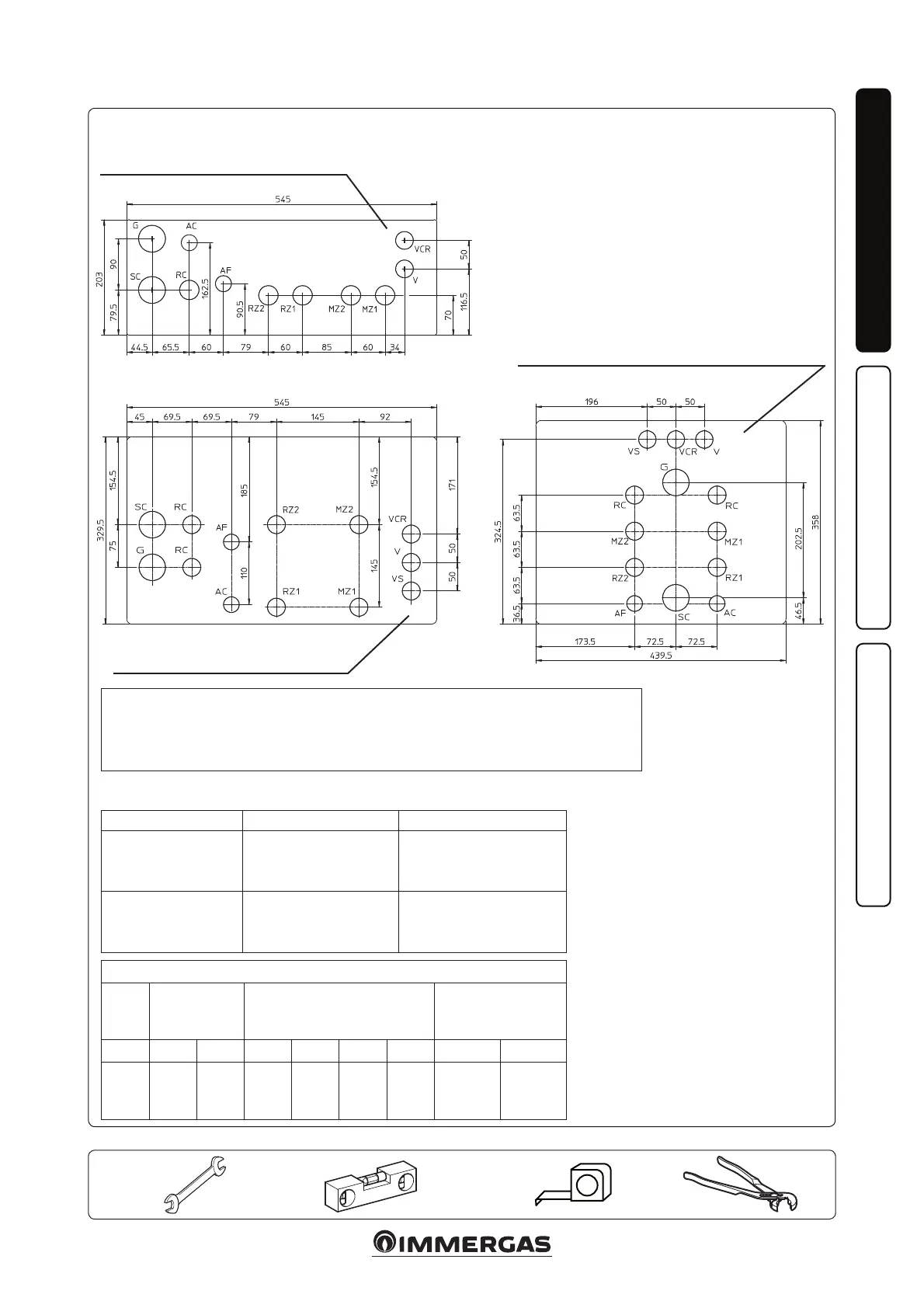
1.5 CONNECTION TEMPLATE.
Attention: the indicated values refer to the stickers applied inside the recessed frame.
Key:
G - Gas supply
AC - Domestic hot water outlet
AF - DHW (Domestic hot water) water
inlet
LP - Chiller line - liquid phase
GP - Chiller line - gaseous phase
MZ1 - Zone 1 system ow
MZ2 - Zone 2 system ow
RZ1 - Zone 1 system return
RZ2 - Zone 2 system return
RC - DHW (Domestic hot water)
recirculation G 1/2"
SC - Condensate drain
V - Electrical connection
VCR - Comando Amico Remoto remote
control - Zone Remote Panel
VS - 3 bar discharge valve
RIGHT HAND SIDE CONNECTION
REAR CONNECTION
LOWER CONNECTION
ZONE CONNECTION TABLE.
Zone 1 Zone 2
Magis Pro
Magis Pro V2
High temperature zone
(direct zone)
Low temperature zone
(mixed zone)
Optional
Magis Combo Plus
Magis Combo Plus
V2
High temperature zone
(direct zone)
Low temperature zone
(mixed zone)
Optional
Connections
GAS
WATER
DOMESTIC
CW
SYSTEM CHILLER LINE
G AC AF RZ1 MZ1 RZ2 MZ2 LP GP
G
1/2”
G
1/2”
G
1/2”
G
3/4”
G
3/4”
G
3/4”
G
3/4”
3/8" SAE
1/4" SAE
(V2)
5/8”
SAE
ATTENTION
In the references in the boiler instructions manual, the mixed zone
corresponds to zone 2 while the direct zone corresponds to zone 1