47
INSTALLERUSER
MAINTENANCE TECHNICIAN
1.37 CIRCULATION PUMP
SOLAR THERMAL SYSTEM
COUPLING KIT.
e units are supplied with circulating
pumps tted with speed regulator.
These settings are suitable for most
systems.
In fact, the pump is equipped with
electronic control to set advanced
functions. For proper operation one
must select the most suitable type of
operation for the system and select
a speed in the available range, with a
focus on energy savings.
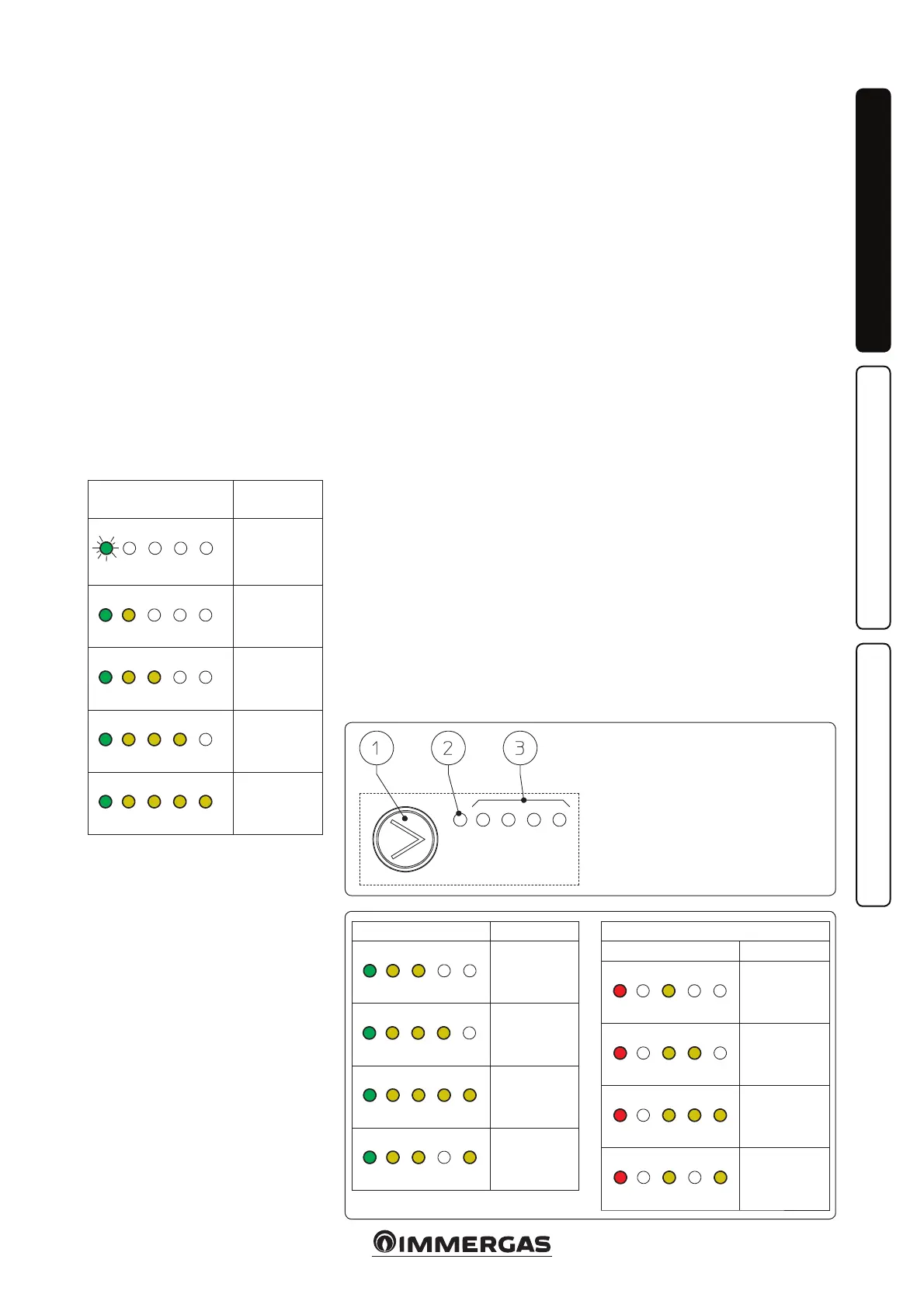
Display of operation status. During
normal operation the status LED (2)
is on green (ashing (FL) when it is in
stand-by), the four yellow LEDs (3) in-
dicate circulator absorption according
to the following table:
Circulating pump
LED
Absorption
GY Y Y Y
FL O O O O
Circulator in
stand-by
GY Y Y Y
On On O O O
0 ÷ 25 %
GY Y Y Y
On On On O O
25 ÷ 50 %
GY Y Y Y
On On On On O
50 ÷ 75 %
GY Y Y Y
On On On On On
75 ÷ 100 %
Selection of operating mode. To s ee
the current operation mode it is su-
cient to press button (1) once.
To change operation mode press the
button for between 2 to 10 seconds
until the current conguration ash-
ing, each time the button is pressed
all possible functions are scrolled
cyclically according to the table (Fig.
55). Aer a few seconds without doing
any operation the circulator memorises
the selected mode and goes back to
operation display.
- Constant curve: the pump operates
with a constant curve. e circulator
working point will move up or down
according to the system's demand.
- PWM prole: do not use this opera-
tion mode.
Selection button lock. e button has
a feature that locks its operation to pre-
vent accidental modications, to lock
the control panel it is necessary to press
button (1) longer than 10 seconds (dur-
ing which the current conguration
ashes), the active lock is signalled by
all LEDs of the control panel ashing.
To unlock the button press again longer
than 10 seconds.
Real time diagnostics: in the event
of malfunction the LEDs provide in-
formation on the circulator operation
status, see table (Fig. 56):
Key:
1 - Function selection button
2 - Green (G) / red (R) LED
3 - 4 yellow LEDs (Y)
54
55
Circulating pump LED
Description
GY Y Y Y
On On On O O
Constant
curve speed 1
GY Y Y Y
On On On On O
Constant
curve speed 2
GY Y Y Y
On On On On On
Constant
curve speed 3
GY Y Y Y
On On On O On
Constant
curve speed 4
(default)
DO NOT USE
Circulating pump LED
Description
RY Y Y Y
On O On O O
PWM Prole
speed 1
RY Y Y Y
On O On On O
PWM Prole
speed 2
RY Y Y Y
On O On On On
PWM Prole
speed 3
RY Y Y Y
On O On O On
PWM Prole
speed 4