42
INSTALLERUSER
MAINTENANCE TECHNICIAN
1
2
3
4
5
6
7
6
10
11
1
4
8
12
9
14
2
13
3
5
1
IN
OUT
2
9
8
11
4
5
7
12
6
13
e expansion vessel must be charged
to:
1.5 bar + 0.1 bar for every metre of the
water column.
“metre of the water column” means
the vertical distance that is present
between the expansion vessel and the
solar collector.
Example:
e circulation unit is found on the
ground oor and the solar collector
is found on the roof at a hypothetical
height of 6 m, the distance to be cal-
culated is:
6 m x 0.1 bar = 0.6 bar
therefore the expansion vessel must be
charged to:
1.5 + 0.6 = 2.1 bar
Solar hydraulic unit safety valve.
ere is a safety valve present on the
hydraulic unit that protects the system
from an excessive increase in pressure.
is valve intervenes by discharging
the liquid contained in the circuit when
the pressure reaches 6 bar.
If the safety valve intervenes and there-
fore part of the liquid contained in the
circuit is lost, it must be re-integrated.
1.32 COOLING / CENTRAL
HEATING CIRCUIT / C.H.
CIRCUIT SYSTEM FILLING.
Once hydraulically installed, proceed
with system lling via the lling cock
/ tap. Filling is performed at low speed
to ensure release of air bubbles in the
water via the Internal Unit and central
heating system vents.
e pumps can be noisy on start-up
due to the presence of air. is noise
should stop after a few minutes of
functioning and however aer having
correctly bled the air contained in the
hydraulic circuit.
Make sure that the vent hoods are loos-
ened. Open the radiator vent valves.
Close radiator vent valves when only
water escapes from them.
Close the lling cock / tap when the
pack or Internal Unit manometer /
pressure gauge indicates approx. 1.2
bar.
N.B.: during these operations, enable
the automatic vent functions on the
Internal Unit (active on rst ignition).
Start the pumps of the hydronic unit
by activating the kit via the relative
remote panel.
1.33 FILLING THE SOLAR
CIRCUIT SYSTEM
OPTIONAL.
e system can only be lled when:
- the system is completely assembled;
- any processing residues that cause
obstructions and through time dete-
riorate the features of the glycol have
been eliminated;
- any presence of water in the system
has been eliminated, which could
otherwise cause damage to the system
in winter;
- the absence of leaks has been veried
by checks using air;
- the storage tank unit has been lled;
- the expansion vessel has been charged
according to system requirements.
e system must be lled using only
the glycol supplied by Immergas via an
automatic pump. e system must be
lled with vent valve closed.
Proceed as follows to ll the system
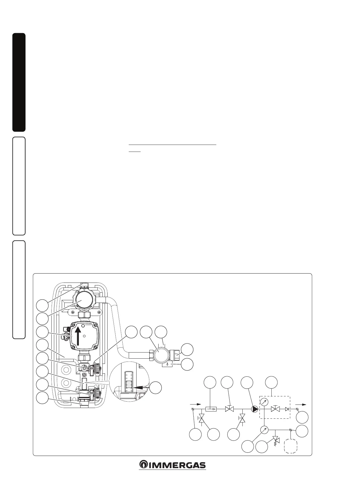
(Fig. 49):
1 connect the automatic pump ow
pipe to the lling cock / tap tting
(9) positioned below the pump and
open the valve itself.
2 connect the automatic pump return
pipe to the draining cock / tap tting
(8) and open the draining valve.
49
Key:
1 - Solar circulator pump
2 - Non return valve, thermometer and cock
3 - Safety valve drain tting
4 - Flow meter
5 - 6 bar safety valve
6 - 3/4” connection for expansion vessel
7 - Pressure gauge
8 - Draining cock / tap
9 - Filling cock / tap
10 - Insulating casing
11 - Flow rate regulator
12 - Inlet
13 - Outlet
14 - Reference for ow rate reading