43
INSTALLERUSER
MAINTENANCE TECHNICIAN
3 e ow rate regulator adjustment
screw (11) must be horizontal in
order to guarantee closure of the
integrated ball valve. Open the ball
valve with thermometer (2) posi-
tioned over the pump.
4 ll the lling pump tank with the
amount of glycol necessary plus a
minimum stock to be le on the bot-
tom of the tank in order to prevent
air circulating inside the circuit.
5 e lling phase must have mini-
mum duration of 20 ÷ 25 minutes.
is time is required to completely
remove all air from the circuit. Every
now and again open the ow rate
regulator adjustment screw in order
to eliminate air from inside (vertical
position).
6 Eliminate any air in the solar circuit
preferably using the so-called "pres-
sure shot" method, which consists
in raising the lling pressure of the
circuit followed by a quick opening
of the return valve (8). is method
allows air to be expelled from the
circuit.
7 Close the filling cock / tap and
switch the lling pump o, open
the adjustment screw of the ow
rate regulator (notch in vertical
position).
8 Leave the circuit pressurised. Any
pressure drop indicates a leak in the
system.
9 Set the functioning pressure in
the circuit at 1.5 bar + 0.1 bar
for every metre in the distance
between the solar collector and
the expansion vessel (practically,
set the same pressure between
expansion vessel and system).
N.B.: Do not exceed 2.5 bar.
10 Switch the solar pump on at a max-
imum speed and make it function
for at least 15 minutes.
11 Disconnect the filling pump and
close the ttings using the relevant
screwing plugs.
12 Open the ball valve above the pump
completely.
Do not ll the system in conditions
with strong insolation and with the
manifolds at high temperatures.
Make sure that all air bubbles have
been completely eliminated.
1.34 SIZING THE SYSTEMS.
e ow temperatures to the various
system zones may be reduced com-
pared to the Internal Unit outlet tem-
peratures, according to the mixture of
the ow and return uids inside the
manifold of the hydronic unit including
the second optional zone installed. In
the event that the two-zone hydronic
unit is used to feed mixed zones, check
that the design parameters allow you to
achieve a maximum surface tempera-
ture of the radiant oor in compliance
with national standards in force.
1.35 KITS AVAILABLE ON
REQUEST.
• System shut-off valves kit (on re-
quest). The kit is designed for the
installation of system interception
cocks, to be placed on the ow and
return pipes of the connection assem-
bly. is kit is particularly useful for
maintenance as it allows the kit to be
drained separately without having to
empty the entire system.
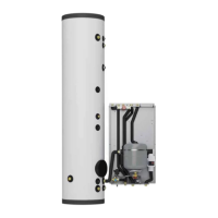
• Connection unit (on request). e
system is dispatched from the factory
without the connection unit. e kit
includes the pipes and fittings for
connecting the pack. It is also possi-
ble to select the connection choosing
between the kit with bottom, rear or
side connection.
• Solar heating system coupling kit.
e system is designed to be com-
bined with the thermal solar system
as supplementary energy source. e
coupling kit is supplied complete with
expansion vessel, circulation unit and
solar control unit.
• Second mixed zone additional kit.
An independent mixed zone is add-
ed using this kit (second zone) for
coupling the Internal Unit inside the
Super Trio.
e above-mentioned kits are supplied
complete with instructions for assem-
bly and use.