29
INSTALLERUSER
MAINTENANCE TECHNICIAN
35
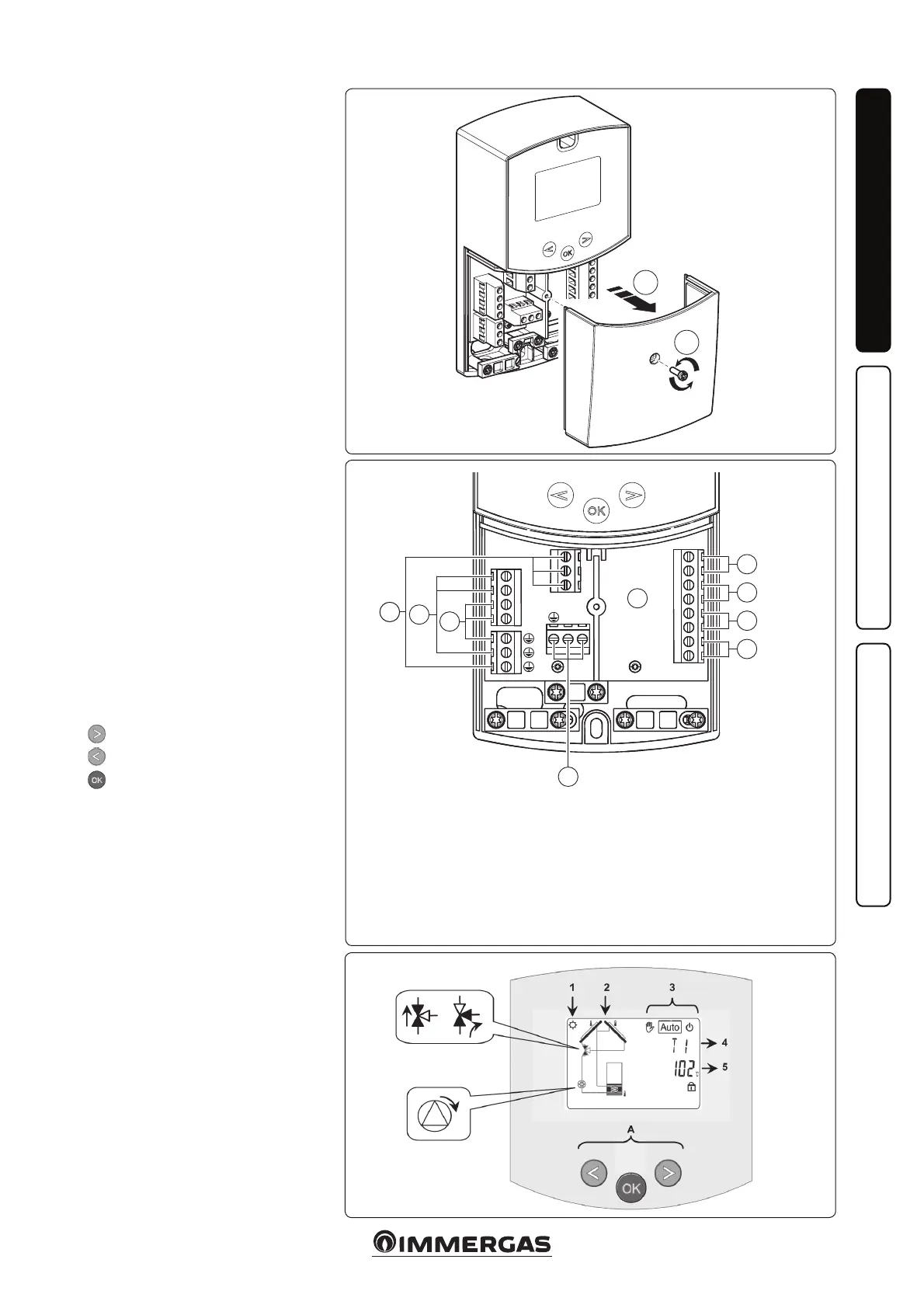
Key:
A Control Unit;
1 Tank 1 sensor (T2) NTC 10k (105°C, 3M);
2 Manifold 1 sensor (T1) PT1000 (180°C, 1.5M);
3 Extra sensor for manifold 2 - (T4) PT1000 (180°C);
4 Extra sensor (T3) NTC 10k (105°C, 3M);
5 Power supply (230 Vac ± 10% - 50Hz);
6 Solar pump (P1);
7 Extra pump or valve (P2);
8 Extra pump or valve (P3) (dry contacts).
36
1.14 ROOM CHRONO
THERMOSTATS AND
REMOTE CONTROLS
OPTIONAL.
See the Internal Unit instruction
booklet.
1.15 SOLAR CONTROL
UNIT INSTALLATION
OPTIONAL.
If necessary, it is possible to remove the
contact cover, by undoing the relevant
xing screw (Fig. 34) and access the
connections area (Fig. 35).
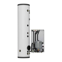
Description of the solar control unit
controls.
1: e solar power storage tank is in
operation.
2: Simplied system drawing.
- e pump logos switch on when
they are activated.
- e solid triangles on the valve
logo indicate circulation.
- The inside of the tank is active
during lling.
3: Operating mode setting.
4: Name of the value or parameter
displayed under number “5”.
5: Temperature of the various sensors
or value of the parameter displayed
under number “4”.
A: Keypad description:
Plus key (▶+);
Minus key (-◀);
Conrmation key or menu navi-
gation key (OK).
N.B.: on the main screen you can
select the sensor that must always be
displayed; press the (OK) key to display
the desired sensor.
Installation menu.
Press the (OK) key for 5 seconds to
access the installation menu.
When you access the installation menu
(the rst parameter “Syst” is displayed),
it is possible to select another parame-
ter by pressing the (OK) navigation key.
Once the desired parameter is dis-
played, it is possible to change the value
using the keys (▶+) or (-◀).
34
A
5
1
2
3
4
7
8
6
1
2