9
INSTALLERUSER
MAINTENANCE TECHNICIAN
5
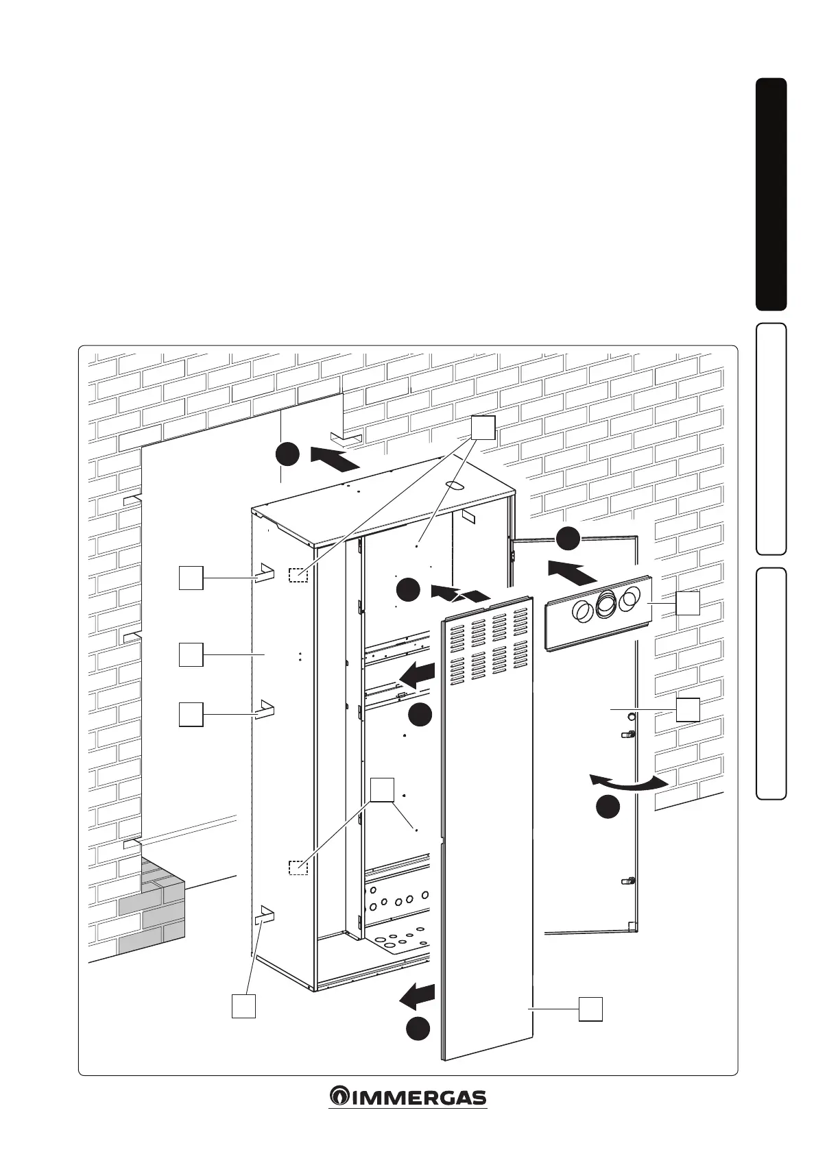
Installation operations.
• Set-up the masonry jobs creating an
opening in the wall where the frame
will be installed (D), paying attention
to envision the space for the six slots
for inserting the respective support
ns (D2) and a space under the frame
sucient to carry out the kit connec-
tions (Fig. 5).
N.B.: it is very important to provide a
support screed in the area under the
Super Trio at the support point of the
storage tank.
• It is also possible to x the frame to
the wall with plugs (not supplied)
using the special four holes Ø 8 mm
(D1).
• e Super Trio is closed by the side
cover (C), where the air intake grid is
present, by the upper cover (B) where
it is possible to let the ue out and by
the door (A) which can be opened
by the handle and only aer having
unlocked the locks placed vertically
to access the thermal kits and the
hydronic unit.
Attention: e installation of the Super
Trio inside the wall, must guarantee
a stable and eective support to the
appliance it contains. is kit ensures
a suitable support only if inserted cor-
rectly (according to the rules of good
practice) and positioned in square
with respect to the wall following the
instructions given below, thus guar-
anteeing the correct functionality of
the front doors. e Super Trio is not
a supporting structure and cannot
replace the piece of wall removed. It is
therefore necessary to check its correct
positioning inside the wall.
2
4
3
5
3
1
B
A
C
D1
D1
D2
D2
D
D2