9
b
2
3
d
a
1
c
2
8
INSTALLERUSER
MAINTENANCE TECHNICIAN
13
1.9 ELECTRICAL CONNECTION.
e appliance has an IPX5D protection degree; electrical safety of
the appliance is achieved only when it is connected properly to an
ecient earthing system, as specied by current safety standards.
ATTENTION:
the manufacturer declines any respon-
sibility for damage or physical injury
caused by failure to connect the boiler
to an ecient earthing system or failure
to comply with the reference standards.
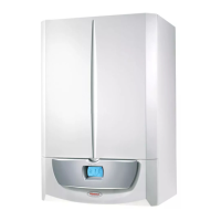
• Open the control panel connections compartment (Fig. 8).
To carry out electrical connections, all you have to do is open the
connections compartment as follows:
- Disassemble the cover (Fig. 54).
- Disassemble the cover (b) as follows:
1. Loosen the screw (a).
2. Press the two hooks on the connections compartment
cover.
3. Remove the cover (b) from the control panel (c).
- At this point, it is possible to access the terminal board (d).
Also ensure that the electrical installation corresponds to maxi-
mum absorbed power specications, as shown on the boiler data
nameplate. Boilers are supplied with a special “X” type power
cable without plug.
ATTENTION:
the power supply cable must be connect-
ed to a 230V ±10% / 50Hz mains supply
respecting L-N polarity and earth con-
nection ; this network must also have
a multi-pole circuit breaker with class III
overvoltage category in compliance with
installation regulations.
To protect from possible dispersions of DC voltage, it is necessary
to provide a type A dierential safety device.
If the power cable is damaged, contact a qualied company (e.g.
the Authorised Aer-Sales Technical Assistance Service) for its
replacement to avoid a hazard.
e power cable must be laid as shown (Fig. 7).
If the network fuse on the P.C.B. needs replacing, this must also
be done by qualied personnel: use a 3.15 A fast fuse.
For the main power supply to the appliance, never use adapters,
multiple sockets or extension leads.
Installation with system operating at direct low temperature.
e boiler can directly supply a low-temperature system by setting
the ow temperature adjustment range “t0” and “t1” (Par. 3.11).
In this situation it is good practice to insert a relevant safety kit
(optional) made up from a thermostat (with adjustable tempera-
ture). e thermostat must be positioned on the system ow pipe
at a distance of at least 2 metres from the boiler.
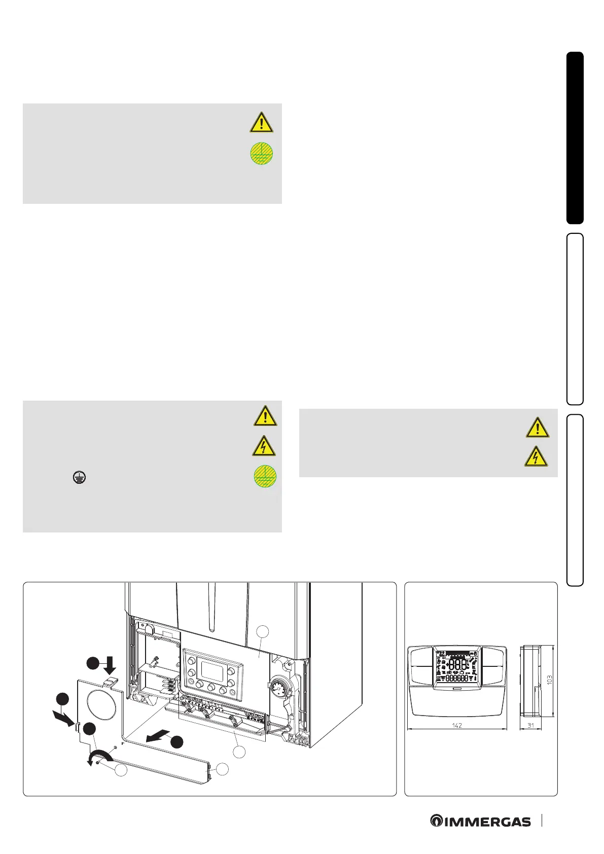
1.10 REMOTE CONTROLS AND ROOM CHRONO
THERMOSTATS OPTIONAL.
e boiler is prepared for the application of room chrono-ther-
mostats or remote controls, which are available as optional kits
(Fig. 9).
All Immergas chrono-thermostats are connected with 2 wires
only. Carefully read the user and assembly instructions contained
in the accessory kit.
ATTENTION:
disconnect power to the appliance be-
fore any electrical connection.
 Loading...