16
17
INSTALLERUSER
MAINTENANCE TECHNICIAN
20
1.15 INTERNAL INSTALLATION USING A RECESSED
FRAME WITH DIRECT AIR INTAKE.
• Conguration type B, open chamber and fan assisted.
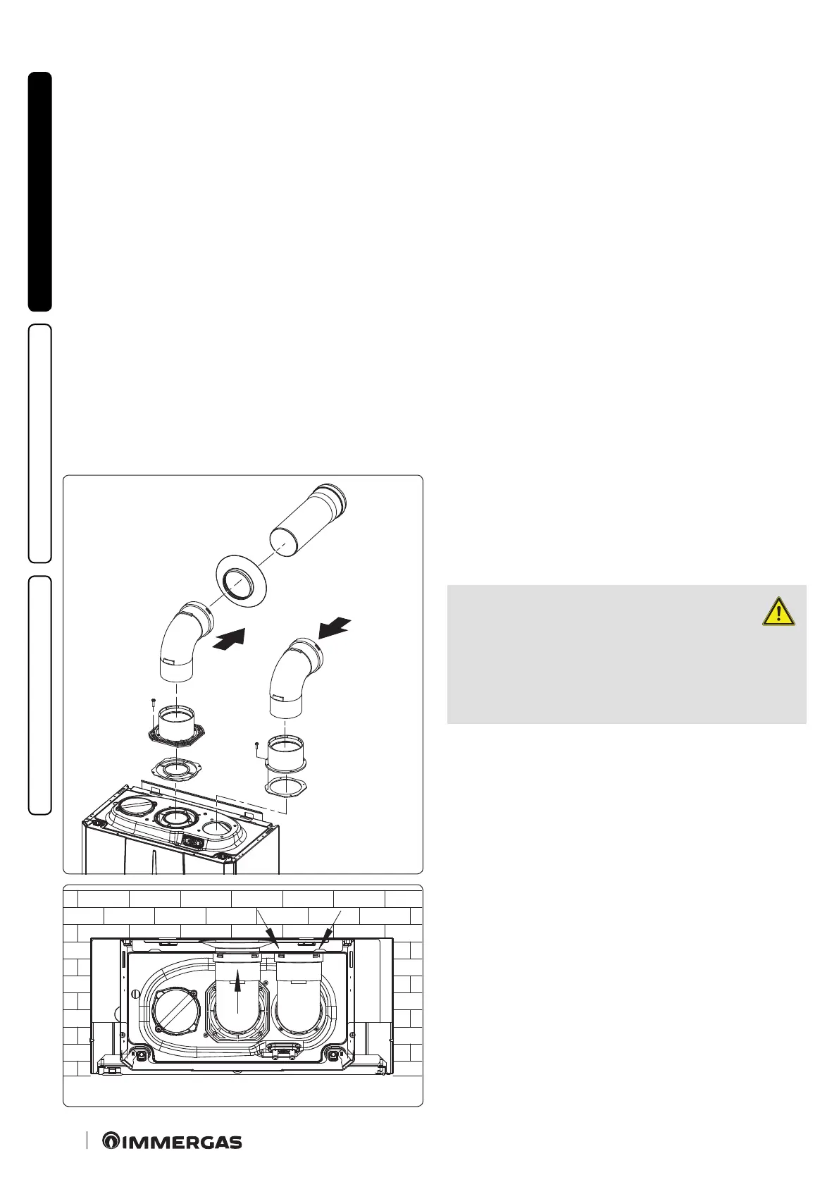
Using a kit separator, one can achieve direct air intake (Fig. 17)
and ue exhaust in a single chimney or directly outside. In this
conguration the boiler is classied as type B
23
.
With this conguration:
- air intake takes place directly from the environment in which
the appliance is installed (the recessed frame is ventilated), and
only functions in permanently ventilated rooms;
- the ue exhaust must be connected to its own individual chimney
or channelled directly into the external atmosphere.
e technical regulations in force must be respected.
Separator kit installation (Fig. 16)
Install the discharge ange on the central hole of the boiler, posi-
tioning the relative gasket with the circular projections downwards
in contact with the boiler ange, and tighten using the hex screws
with at tip contained in the kit. Remove the at ange present
in the lateral hole with respect to the central one (according to
needs) and replace it with the intake ange, positioning its gas-
ket already present in the boiler and tighten using the supplied
self-threading screws. Fit the male side (smooth) to the bends in
the female side of the anges.
e intake bend must face the rear side of the boiler.
Fit the exhaust pipe with the male side (smooth) to the female
side of the bend up to the end stop, making sure that the internal
wall sealing plate has been tted and connecting the required ue
according to personal requirements.
Max. length of exhaust pipe.
e exhaust pipe (both vertical or horizontal) can be extended to
a max. length of 30 linear metres.
1.16 CONCENTRIC HORIZONTAL KIT INSTALLATION.
• Type C conguration, sealed chamber and fan assisted.
e position of the terminal (in terms of distances from openings,
overlooking buildings, oor, etc.) must be in compliance with the
regulations in force.
is terminal is connected directly to the outside of the building
for air intake and ue exhaust. e horizontal kit can be installed
with the rear, right side, le side or front outlet. For installation
with frontal outlet, one must use the xing plate and a concentric
bend coupling in order to ensure sucient space to carry out the
tests required by law upon commissioning.
• External grid.
Both the Ø 60/100 and Ø 80/125 intake/exhaust terminal, if prop-
erly installed, is pleasant to look at on the outside of the building.
Make sure that the external silicone wall sealing plate is properly
inserted in the wall.
ATTENTION:
for correct functioning of the system
the terminal with grid must be in-
stalled correctly ensuring that, the "high"
indication present on the terminal is respect-
ed on installation.



 To Next Page