39
INSTALLERUSER
MAINTENANCE TECHNICIAN
43
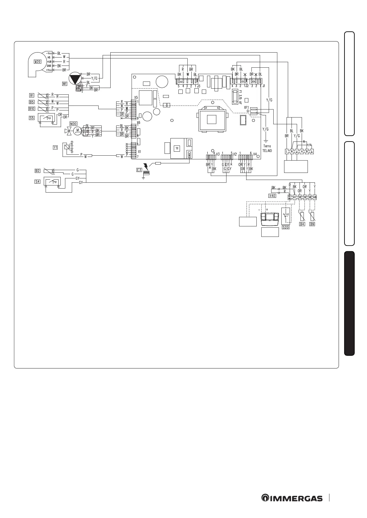
3.5 WIRING DIAGRAM.
Key:
B1 - Flow probe
B2 - DHW probe
B4 - External probe (optional)
B5 - Return probe
B9 - DHW inlet probe (optional)
B10 - Flue probe
CAR
V2
- Comando Amico Remoto
V2
remote control
(optional)
E3 - Ignition and detection electrode
M1 - Boiler pump
M20 - Fan
M30 - ree-way motor stepper
S4 - D.H.W. ow switch
S5 - System pressure switch
S20 - Room thermostat (optional)
T2 - Ignition transformer
X40 - Room thermostat jumper
Y1 - Gas valve
Colour code key:
BK - Black
BL - Blue
BR - Brown
G - Green
GY - Grey
OR - Orange
P - Purple
PK - Pink
R - Red
W - White
Y - Yellow
Y/G - Yellow/Green
Comando Amico Remoto remote control
V2
.
e boiler is prepared for the application of the Comando Amico
Remoto remote control
V2
(CAR
V2
), which must be connected to
clamps 44/40 and 41 of the terminal board (located in the boiler
control panel) respecting the polarity and eliminating jumper X40.
Room thermostat.
e boiler is prepared for the application of the room thermo-
stat (S20), which must be connected to clamps 44/40 - 41 of the
terminal board (located in the boiler control panel) eliminating
jumper X40.
Power supply
230 Vac
50Hz
IMG BUS
(optional)
CAR v2
(optional)
 Loading...