C
33
C
33
C
33
C
33
7
4
6
5
1
2
3
1
2
3
4
5
6
7
22 23
24 25
INSTALLERUSER
MAINTENANCE TECHNICIAN
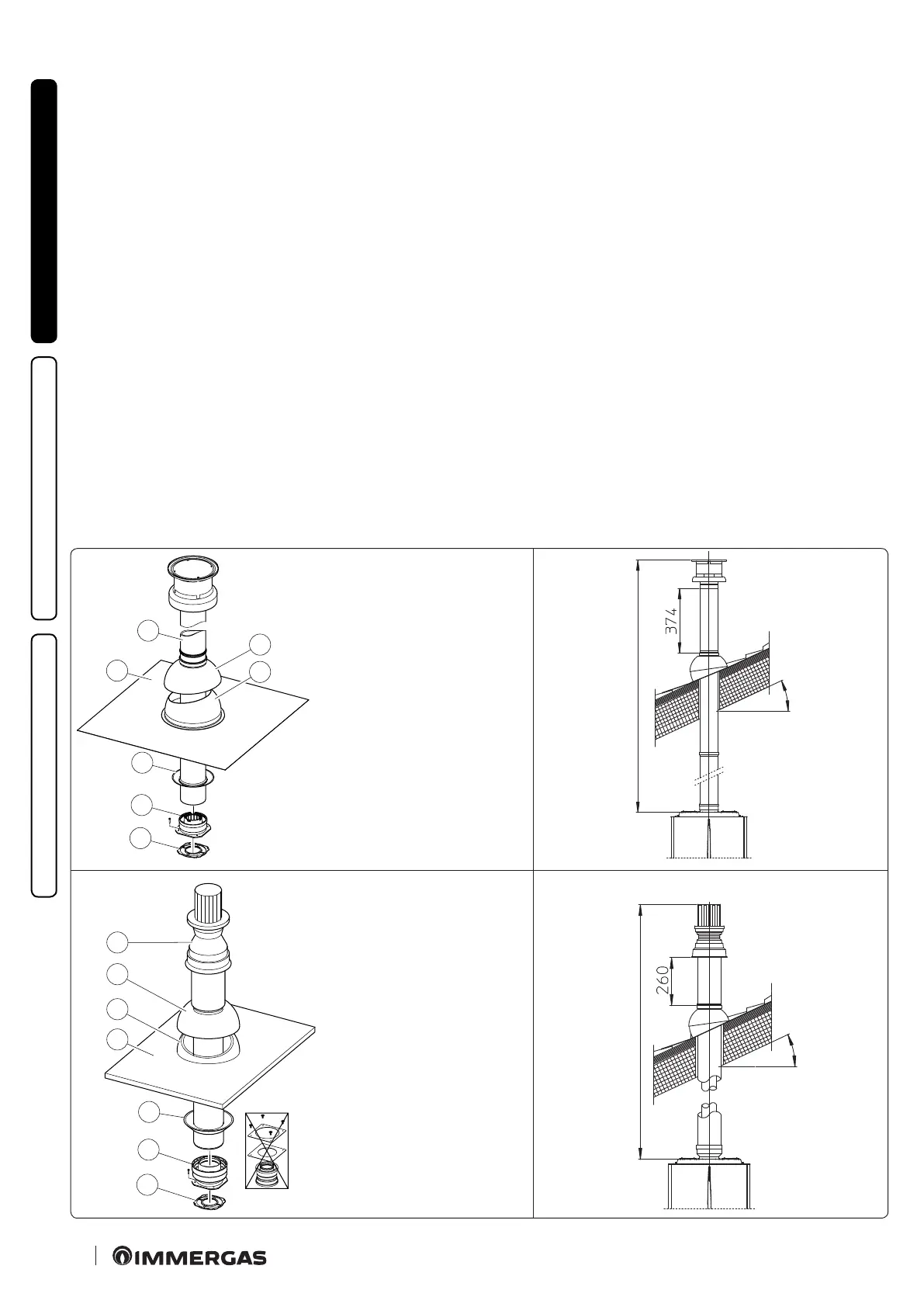
22
e Kit includes:
N° 1 - Gasket (1)
N° 1 - Female concentric ange (2)
N° 1 - Wall sealing plate (3)
N° 1 - Aluminium tile (4)
N° 1 - Int./exhaust concentric pipe
Ø 60/100 (5)
N° 1 - Fixed half-shell (6)
N° 1 - Mobile half-shell (7)
e adaptor kit includes:
N° 1 - Gasket (1)
N° 1 - Adapter
Ø 80/125 (2)
e Kit Ø 80/125 includes:
N° 1 - Wall sealing plate (3)
N° 1 - Aluminium tile (4)
N° 1 - Fixed half-shell (5)
N° 1 - Mobile half-shell (6)
N° 1 - No.80/125 - Int./exhaust
concentric pipe (7)
e remaining kit components
must not be used
Vertical kit with aluminium tile Ø 60/100. Kit assembly
(Fig. 22).
Install the concentric ange (2) on the central hole of the boiler,
positioning gasket (1) with the circular projections downwards
in contact with the boiler ange, and tighten using the screws
contained in the kit.
Installation of the fake aluminium tile: replace the tiles with the
aluminium sheet (4), shaping it to ensure that rainwater runs o.
Position the xed half-shell (6) on the aluminium tile and insert
the intake-exhaust pipe (5). Fit the Ø 60/100 concentric terminal
pipe with the male side (5) (smooth) into the ange (2) up to the
end stop; making sure that the wall sealing plate has been tted
(3), this will ensure sealing and joining of the elements making
up the kit.
N.B.: when the boiler is installed in areas where very rigid temper-
atures can be reached, a special antifreeze kit is available that can be
installed as an alternative to the standard kit.
• Extensions for vertical kit Ø 60/100 (Fig. 23).
e kit with this conguration can be extended to a max. straight
vertical length of 14.4 m, including the terminal. is congura-
tion corresponds to a resistance factor of 100. In this case specic
extensions must be requested.
Vertical kit with aluminium tile Ø 80/125. Kit assembly
(Fig. 24).
To install the kit Ø 80/125 one must use the anged adapter kit
in order to install the ue system Ø 80/125. Install the anged
adaptor (2) on the central hole of the boiler, positioning gasket
(1) with the circular projections downwards in contact with the
boiler ange, and tighten using the screws contained in the kit.
Installation of the fake aluminium tile: replace the tiles with the
aluminium sheet (4), shaping it to ensure that rainwater runs o.
Position the xed half-shell (5) on the aluminium tile and insert
the intake-exhaust pipe (7). Fit the Ø 80/125 concentric terminal
pipe with the male end (smooth) to the female end of the adapter
(1) (with lip gasket) up to the stop; making sure that the wall seal-
ing plate (3) has been tted, this will ensure sealing and joining
of the elements making up the kit.
• Extensions for vertical kit Ø 80/125 (Fig. 25).
e kit with this conguration can be extended up to a max. length
of 32 m including the terminal. If additional components are
assembled, the length equivalent to the maximum allowed must
be subtracted. In this case specic extensions must be requested.
Max. 14400 mm)
Max. 32000 mm
Max. 45%
Max. 45%
 Loading...