Specifications 9-22
9
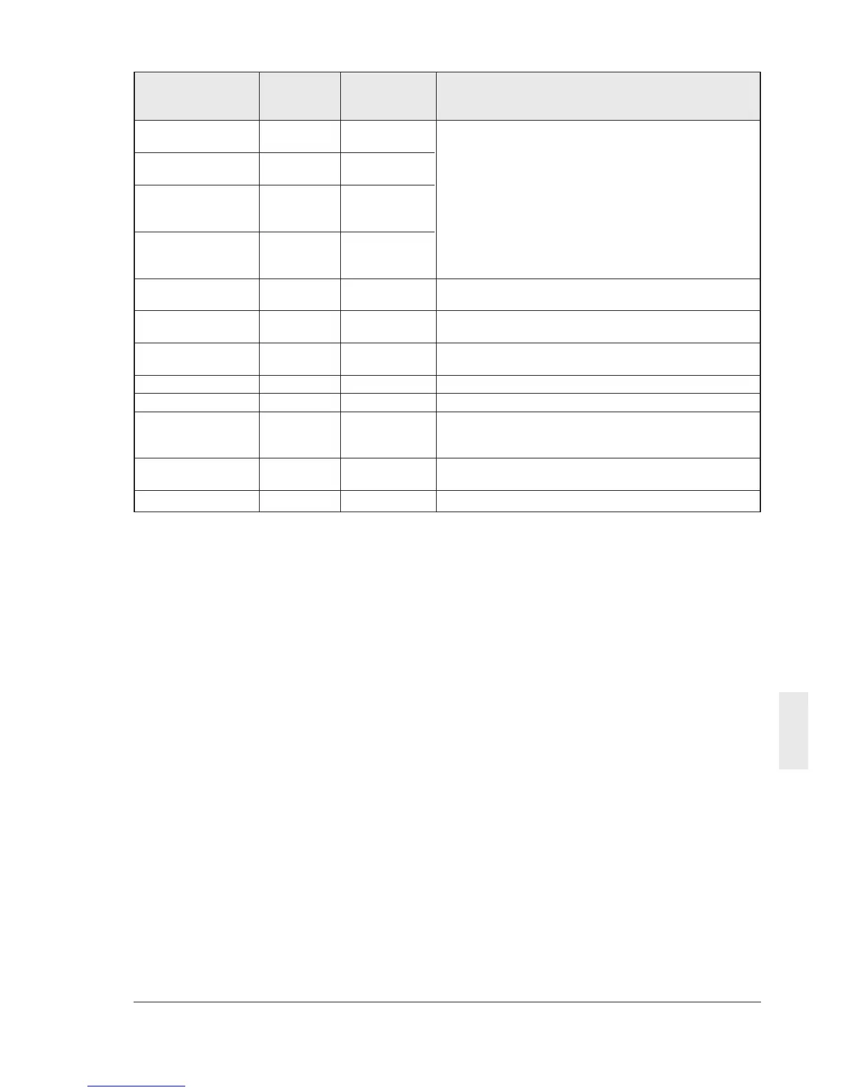
Name Command Function type Data and operation
type character and
character number
Failure description; R M16
current one
Failure description; R M17
previous one
Failure description; R M18 Refer to (4) Alarm display data
one before
previous one
Failure description; R M19
one before two
previous ones
Total operation R M20 0 to 65535 / 0 to 65535 hours
time
DC link voltage R M21 0 to 500 / 0 to 500V (200V class)
monitor 0 to 1000 / 0 to 1000V (400V class)
Function code R M23 4112H = VXSM-1
4114H = VXSM-3
Capacity code R M24 1=0.01kW
ROM version R M25 0 to 99: Standard, > 100: Non-standard
Transmission error R M26 Refer to section 9-4-9. The latest error is returned.
handling code The communication error is initialized when the power
is turned off.
Main circuit R M46 1=0.1%
capacitor life
Cooling fan life R M48 1=1 hour
Note)
1) Output frequency monitoring (M09, M35) adds
an ASCII code for forward rotation (space), reverse
rotation (minus) and stop (space) as direction of
rotation data, and handled as 5-byte data.