9-23 Specifications
9
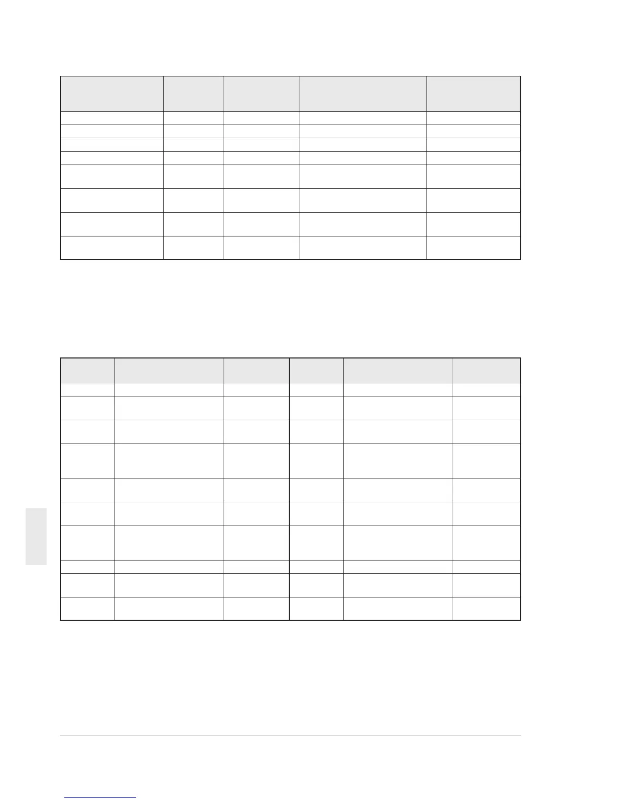
(3) Functions for short frame
Table 9-4-7 Short frame
(4) Alarm display data
The failure description (alarm description) is as
shown in the table below. The failure code is in
the hexadecimal notation.
Table 9-4-8 Failure description
Function Command Data direction Data range; transmission Change
type data / actual data during
character operation
Frequency command a Selecting Same as S01 -
Frequency command e Selecting Same as S05 -
Operation command f Selecting Same as S06 -
Reset command m Selecting 4 spaces -
Calculated torque h Polling Same as M07 -
value monitor
Torque current I Polling Same as M08 -
monitor
Output frequency j Polling Same as M09; no sign . -
monitor is attached
Operation state k Polling Same as M14 -
monitor
Failure Description Indication Failure Description Indication
code on panel code on panel
0000 No alarm --- 0012 External alarm OH2
0001 Overcurrent, during OC1 0016 Braking resistor dbH
acceleration overheat
0002 Overcurrent, during OC2 0017 Motor 1 overload, OL1
deceleration
0003 Overcurrent, during OC3 0018 Motor 2 overload, OL2
constant speed
operation
0006 Overvoltage, during OU1 0019 Inverter overload OLU
acceleration
0007 Overvoltage, during OU2 001F Memory error Er1
deceleration
0008 Overvoltage, during OU3 0020 Keypad panel Er2
constant speed communication error
operation
000A Undervoltage LU 0021 CPU error Er3
000B Input phase loss Lin 0025 Output phase loss error Er7
loss error
0011 Heat sink overheat OH1 0026 RS485 communication Er8
error