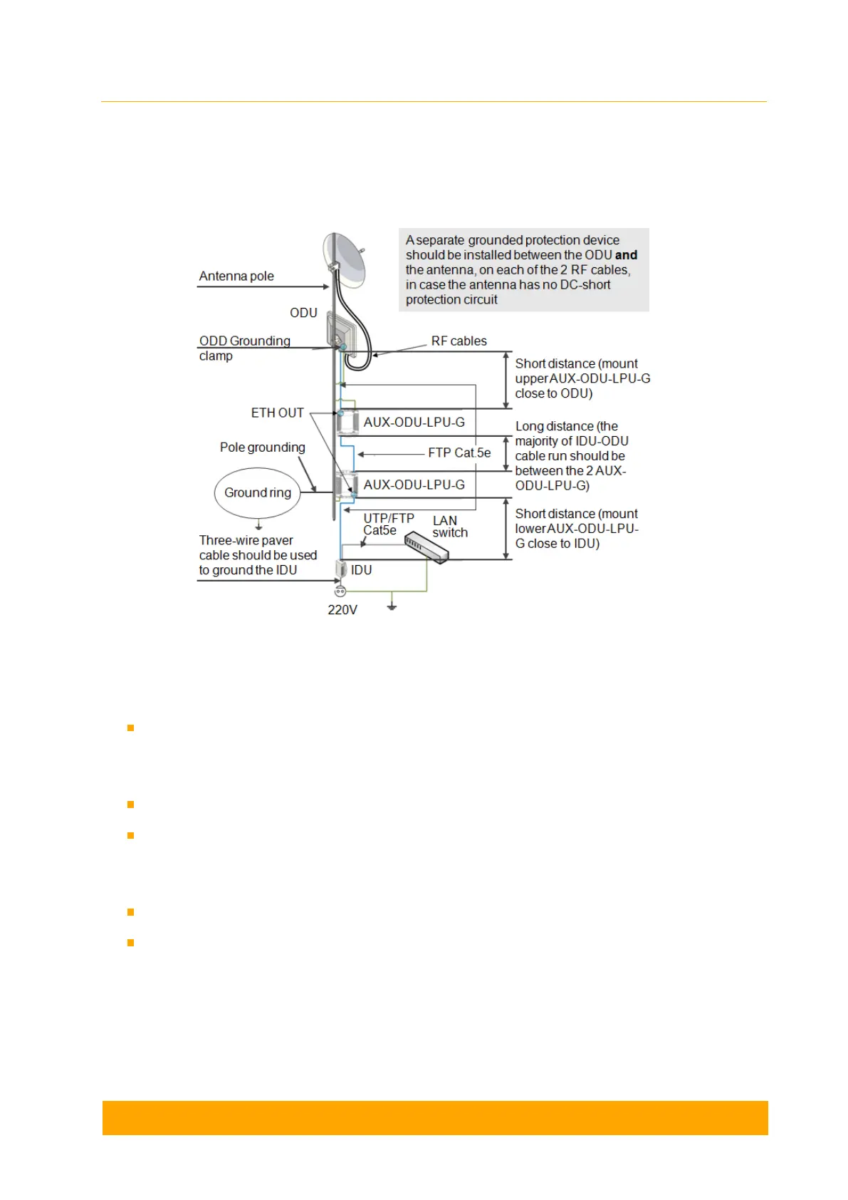
AUX-ODU-LPU-G Grounding Scheme
The grounding and lightning protection initial procedures when using AUX-ODU-LPU-G are
similar to those when using regular IDU.
Figure - AUX-ODU-LPU-G Grounding Scheme
For maximum protection of the ODU, IDU and customer LAN devices, use two AUX-ODU-LPU-
G connected as shown in the diagram:
The purpose of the LPU at the top is to protect the ODU from a surge of lightning strike
which can hit the long FTP cable run along the height of the pole or on the roof of the
building.
The purpose of the LPU at the bottom is to protect the IDU and customer equipment.
Make sure to install the two LPU devices in the correct polarity, as shown in the diagram:
top LPU with "ETH OUT" facing the ODU and bottom LPU with "ETH OUT" facing the
IDU, and the second LPU units connected to each other via "ETH IN".
Install each LPU as close as possible to the device it protects.
The cable length between the top LPU and ODU should be minimum, as well as the
cable length between bottom LPU and IDU. Keep most of the IDU-ODU FTP cable
length between the two LPU devices.