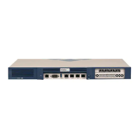
Infoblox SoT 1405 Series Hardware Components
For the Infoblox 1400 Series Platforms 11
IPMI Port Dedicated Ethernet port used for LOM (Lights Out Management) with specific releases of
NIOS. The IPMI/LOM Port supports 10/100 operation only. Ensure that the IPMI port is
properly connected to the network before you configure LOM through the Grid Manager for
remote management. The IPMI port auto-negotiates up to Fast Ethernet 100BASE-TX speeds;
ensure that the switch port to which the IPMI port connects will auto-negotiate to 100Mbps
operation. Follow best practices for IPMI usage in the network by not allowing the IPMI port to
connect to the general-use data center network or to 1 Gbps/10 Gbps switch interfaces.
USB Port Reserved for future use.
Console Port A male DB-9 serial port for a console connection to change basic configuration settings and
view basic system functions through the CLI (command line interface).
If your system lacks a DB-9 serial port, use a properly grounded USB-to-Serial dongle for
connection to the serial console port. If the dongle is connected to a laptop, the laptop also
must be properly grounded. Failure to do so may cause damage to the serial console port of
the Infoblox appliance. Infoblox is not responsible for such damage. For DB-9 pin
assignments, see Figure 4.
MGMT Port A 10/100/1000-Mbps gigabit Ethernet port that you can use for appliance management or
DNS service. You can enable the MGMT port and define its use through the Grid Manager
after the initial setup.
The Advanced Appliance PT-1405 must be managed through its MGMT port.
HA Port (Active for
high availability in
the TE-1400
appliances and
PT-1400)
A 10/100/1000-Mbps gigabit Ethernet port through which the active node in an HA (high
availability) pair connects to the network using a VIP (virtual IP) address. HA pair nodes also
use their HA ports for VRRP (Virtual Router Redundancy Protocol) advertisements.
ND-1405 and TR-1405 Reporting: HA Port inactive and reserved for future use.
LAN1 Port A 10/100/1000-Mbps gigabit Ethernet port that connects the appliance to the network. You
must use the LAN1 port to set up the appliance initially. It handles all traffic if you do not
enable the MGMT and LAN2 ports. The passive node in an HA pair uses this port to
synchronize the database with the active node.
LAN2 Port A 10/100/1000-Mbps gigabit Ethernet port that connects the appliance to the network. The
LAN2 port is disabled by default. You can enable the LAN2 port and define its use through the
Grid Manager after the initial setup.
UID Button The unit identification button. When you press the UID button, the LCD panel on the front
panel blinks and the UID LED on the rear panel glows blue. In a rack environment, the UID
feature enables easier location of a server when moving between the front and rear of the
rack. You can also identify the appliance through the Grid Manager and CLI commands.
Status LED Reserved for future use.
Power LED An LED that glows blue when there is power to the appliance. When it is dark, the appliance is
not receiving power, even if the power cable is plugged in. Ensure that you power on the
appliance through the On/Off switch using a small blunt object, such as a paper clip.
Alarm LED Reserved for future use.
Component Description
 Loading...