NOTE: IT IS VERY IMPORTANT TO HAVE THE AIR PRESSURE REMOVED
FROM THE TRANSDUCER PRIOR TO CALIBRATION.
INTELLISYS INTERFACE BOARD
(SSR 10-40 Horsepower)
Some of the Rev. 3.0 Interface Boards give symptoms of intermittent contact and
open circuits. This can result in various error codes displayed on the Intellisys.
We have learned that the Rev. 3.0 Board has had broken and cold solder joints.
The new Rev. 4.0 should correct this problem.
The Rev. 3.0 and 4.0 have the same I-R part number 39538178. The Rev. 3.0
should no longer be in stock in Davidson Parts Center.
Do not replace the Rev. 3.0 Interface Board unless you have experienced
problems with it.
Contact Customer Service Department in Davidson for techniques in
troubleshooting defective Interface Boards.
INTERFACE BOARD TEST PROCEDURE
Procedure for testing the 115V circuits in the Interface Board
We have experienced problems with different components not operating
electrically. These components could be the 1M contactor, 1SV Load Solenoid,
2SV Modulate Solenoid, and 10SV Line/Sump Solenoid. The problem could be
in an open circuit, or cold solder joint in the Interface Board. The following test
should help in troubleshooting these problems:
1. Remove the power from the machine.
2. Disconnect the two ribbon cables from the Interface Board.
3. As an example, assume you are having a problem with the 1M Contactor
not pulling in. Take an extension cord and connect the two leads to
terminals 8 and 19. Plug in the cord. The contactor should pull in. If it
does, unplug your cord and reconnect the leads in the pins on the white
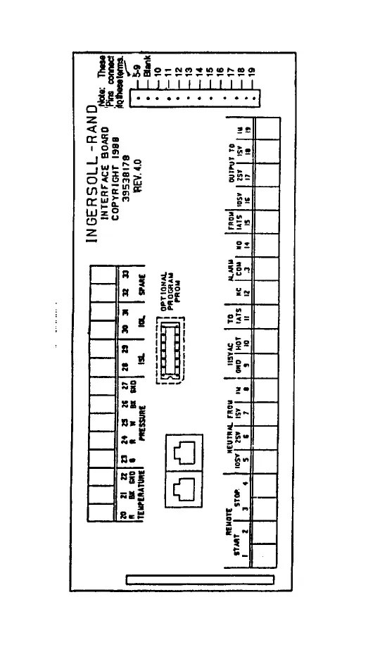
connector that connect to terminals 8 and 19, (see diagram 1).
4. Plug in your extension cord if the 1M contactor does not pull in. The
Interface Board is open on this particular circuit and should be replaced.
5. This test can be done on all of the 115V components that connect to the
Interface Board. Use diagram 1 to determine connection points.
-23- -24-
DIAGRAM 1
 Loading...