E-PROMS AND KIT NUMBERS
50-450 Horsepower P/N
Current main program E-prom 39179593
Auto Start and Stop Prom only 39479399
Remote Start and Stop Prom only 39479423
% Modulation Prom only 39479407
Sequence Control Prom only 39479415
Sequencer Interface I 39805312
Show Prom 39183702
APDD404-90 Instruction Installation
APDD405-90 Instruction Sequencer Controller
TEMPERATURE SENSOR OVERVIEW
Issued 1 February '91
There are three thermistor type temperature sensors used on SSR 50 through
450 horsepower units.
The word "Thermistor" means "thermally sensitive resistor" and is a device that
will change its resistance value as it changes in temperature. The thermistor is
made from a mixture of sintered metal oxides such as manganese, cobalt or
nickel that is sealed within a glass bead. Two wires are attached to the
thermistor device...a Black wire "in" and a White wire "out".
The resistance characteristics of the thermistor will quickly change as the
temperature of its stainless steel housing changes. The thermistor is very
sensitive, very accurate and the resistance value of the device will DECREASE
as the temperature INCREASES.
As an example...there will be approximately 10,000 ohms resistance between
the Black and White wire at 77 degrees F. but only 1,014 ohms resistance at 185
degrees F.
Accordingly, at approximately 77 degrees F. and with 5 volts DC applied to the
Black wire of the thermistor, the voltage allowed through the thermistor will be
reduced to approximately 61 millivolts DC.
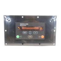
This varying DC voltage from the thermistor is processed by an Analog-To-
Digital converter device and then forwarded to the Intellisys Controller.
Depending on the voltage level, decisions will be made by the Intellisys that may
only change a temperature number on the panel display or could possibly shut
the compressor down if conditions dictate.
Each of the three temperature sensing thermistors is connected to a specific
point on the Analog Board located in the upper portion of the main starter box.
Sensor 2CTT connects to an area marked "T1", 2ATT connects to an area
marked "T2" and 4ATT connects to an area marked "T3". See page 72 for
outline. (Analog Barrier Board)
These three connection areas (T1,T2 and T3) each have three terminal screws
having both a terminal number identification and a wire color identification. As
an example...connection area T1 has 21/WHT, 22/BLK and 23/GND. Accord-
ingly, sensor 2CTT will connect to area T1 with the White wire connected to
-73- -74-
terminal 21, the Black wire connected to terminal 22 and the Ground wire
connected to terminal 23. All three sensors connect to their respective areas of
the Analog Board in a similar manner.
The 5 volt DC source for the sensors is supplied by a small but extremely
accurate voltage regulator mounted on the upper left side of the Analog Board.
The input voltage to this small regulator is approximately 9 volts DC but this 9
volts input may vary up or down in significant amounts as the customer's line
voltage varies. However, the voltage regulator output of 5 volts DC will remain
exactly at 5 volts DC. This 5 volts DC output must remain stable and constant
for the Intellisys Controller logic to function properly.
This constant 5 volt DC signal entering the thermistor will be greatly reduced in
voltage due to the resistance effect of the variable resistor sealed within the
sensor body as the voltage tries to get back to the Analog Board through the
White wire.
The three temperature thermistors used are identical and carry CCN 39541677.
The thermistor housing is made of stainless steel and requires an O-Ring
(39404157) to seal the SAE fitting area of the housing to its installed location.
These thermistors are neither adjustable nor repairable and must be replaced
should one fail.
Because the thermistor is actually part of an assembly, further explanation will
use the word "Sensor" to describe this device.
Operation of the temperature sensors is as follows:
2CTT - Injected Coolant Temperature Sensor
Monitors the temperature of Coolant being injected into the airend that absorbs
heat of compression, lubricates moving components and seals rotor clear-
ances. The sensor is located in the Coolant piping just prior to the Coolant being
injected into the airend.
Sensor (2CTT) sends a variable DC voltage signal to the Intellisys Controller to
provide temperature information for "Injected Coolant Temperature" if that
display has been selected on the Controller panel and instructs the Intellisys to
slightly open the unloaded position of the air inlet valve when the injected
Coolant temperature is lower than 120 degrees F. This slight opening of the inlet
air valve when the unit is cold increases the unloaded sump pressure approxi-
mately 20 PSIG to promote flow of the cold Coolant.
After the temperature of the injected Coolant rises above 120 degrees F., the
signal from 2CTT is interpreted by the Intellisys which then recloses the inlet air
valve the slight amount mentioned in the previous paragraph. The unloaded
sump pressure then drops to the normal level of 24 to 33 PSIG and the
compressor runs unloaded.
One additional feature of 2CTT is that the signal from this thermistor is also used
by the Intellisys to display "Wait-Coolant Too Cold" should the operator select
"Coolant Filter Condition" when the injected Coolant temperature is lower than
120 degree F.
This sensor serves no other function and does not provide a Warn or Alarm
feature that will shut the compressor down.

 Loading...


