INTRODUCTION
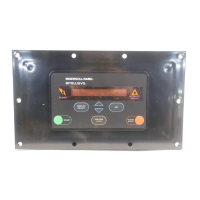
The I-R Intellisys controller is a fully integrated microprocessor based control
unit which replaces all electromechanical components previously used to
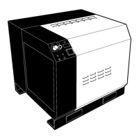
control compressor operation. The Intellisys is applied to the SSR 10-40
horsepower range and is the first in a series of new controllers. This common-
ality of systems will allow more flexibility in operation than has been presently
possible.
This presentation will go through the Intellisys Controller in detail. We will cover
the main components that make up the controller, the sensors used by the
system and operation of the systems default messages and troubleshooting.
COMPONENTS
The SSR 10-40 horsepower Intellisys system is made up of the following
components, the Intellisys box, temperature sensor, pressure sensor, and
starter interface board.
The Intellisys box contains the following major pieces, the membrane switch,
CPU board and plastic enclosure.
The membrane switch is layers of polycarbonate adhered together. The top
layer is the layer that is visible to the operator. Silkscreening is used on the
backside of the top layer to give the maximum durability. This top layer is
embossed by a heat process to help delineate the switch pads. The second
layer of the switch has holes which contain stainless steel domes to provide
tactile feedback to the operator. The third layer has been printed with a
conductive ink. When the metal dome contacts the ink circuit, it completes the
circuit and makes a momentary contact switch. These circuits are arranged in
a matrix grid that terminates in a plug. The fourth layer is the back of the
membrane and it is also printed to provide a static shield.
The layers of the membrane switch are adhered by a 3M adhesive that has been
tested to withstand the effects of a compressor environment including exposure
to Ultra Coolant. The reliability of a membrane is much higher than that of a
mechanical switch.
The enclosure is a injection molded component. Polyester was selected due to
its resistivity to pollutants found in normal environments and its superior
strength. Injection molding was selected as the manufacturing process due to
its high precision.
The CPU Assembly is an Ingersoll-Rand design.
This board is not intended for general service and never requires field trou-
bleshooting.
The Starter Interface Board is the transition between the electrical wiring and the
Intellisys. The large terminal strips are for field accessibility. The Starter
Interface Board is divided into a high level 115 volt AC and a 5 volt DC section.
Each terminal has been clearly identified as to its purpose.
The ribbon cables connecting the starter boards with the Intellisys controller
have been separated the same way. The larger cable is for 115 volt AC signals
and the smaller cable is for 5 volt DC signals.
This is the socket for the option prom and the communications port. Options are
activated by inserting the option prom in the socket. The prom contains
permanent memory which supplies the Intellisys controller with some additional
information required for the respective option and triggers a code in the
microprocessor.
The communications port is for communication with other Ingersoll-Rand
Products.
-1-
-2-
 Loading...


