Programming the SmartLink-GP 29
Programming manual
3.8 Programming the SmartLink-GP as an
Intrusion control panel
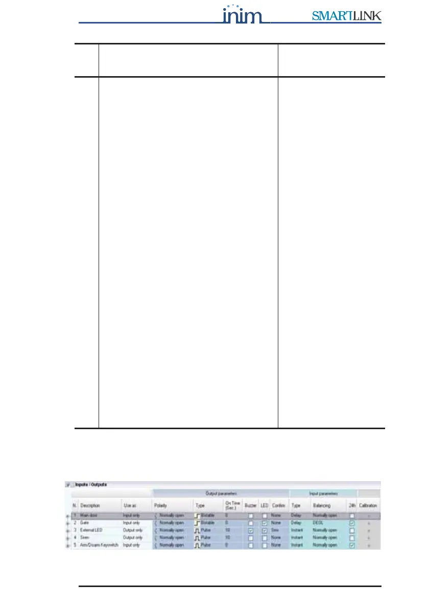
Figure 6 - Inputs/Outputs table
Calibration
The button used to calibrate an input and
reduce the effect of loss of component
characteristics.
a
Proceed as follows:
1. Connect a calibration resistor (10K,
12K or 15K as required, between
IN&OUT terminal concerned and
ground (terminal 4).
2. Connect the SmartLink-GP to a
computer.
3. Select the button in the Resistance
column: the box will show the value
read on the terminal.
4. If the value differs greatly from the
value of the resistor connected to the
terminal, proceed with the
calibration. If the values are very
similar, calibration will not be
necessary.
5. Otherwise, select Calibrate: answer
YES to the confirm request.
6. Click on the value of the resistor used
then select Ok.
SmartLink-GP compares the selected
value and the current value on the
input. It will indicate any notable
difference and request confirmation
to continue.
7. Wait 3-4 seconds: a calibration done
message appears. Select the button
in the Resistance column to verify
the value on the terminal after
calibration.
Send the parameters to
SmartLink-GP before
switching off. This is the
only way to make the
calibration definite!
Calibration is
recommended on
systems using dated
components, in order to
allow signals coming
from these components
to have values suitable
to detect exceeded
balance thresholds and
subsequent status
changes.
You can use the View
button in the
Resistance column at
any time to view the
value of the resistance
on a specific terminal.
The terminal open
string indicates a value
of over 30K.
a. Patent pending
Para-
meter
Description Note