24 Programming the SmartLink-GP
Programming manual
3.7 Programming the Inputs and Outputs —
IN&OUT
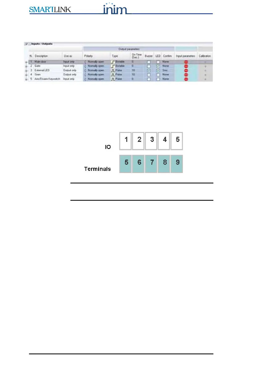
Figure 5 - Inputs/Outputs table
The IN&OUT terminal board provides 5 terminals (5 to 9), each of which can
be used as an input or as an output or both. The Use as drop-down menu
will allow you to select the operating mode of the terminal.
SmartLeague refers to the terminals as “input” or “output” using this
numeration:
Note: In this chapter the terminals are identified by their type
and number (e.g. input 1 or output 3).
Refer to the Installation Manual - paragraph 5.1 Terminal board for the
terminal board.
3.7.1 Inputs
The inputs can be used for devices with two statuses only (active-standby) or
for devices with three or four statuses (e.g. standby, alarm, tamper and
short-circuit).
The four statuses are determined by two termination resistors which
determine the three threshold windows. Each exceeded threshold generates
an event which can be associated with an outgoing SMS text message,
Contact ID report, voice message or activation of outputs and constraint.