31
Version 2.02 December-2002
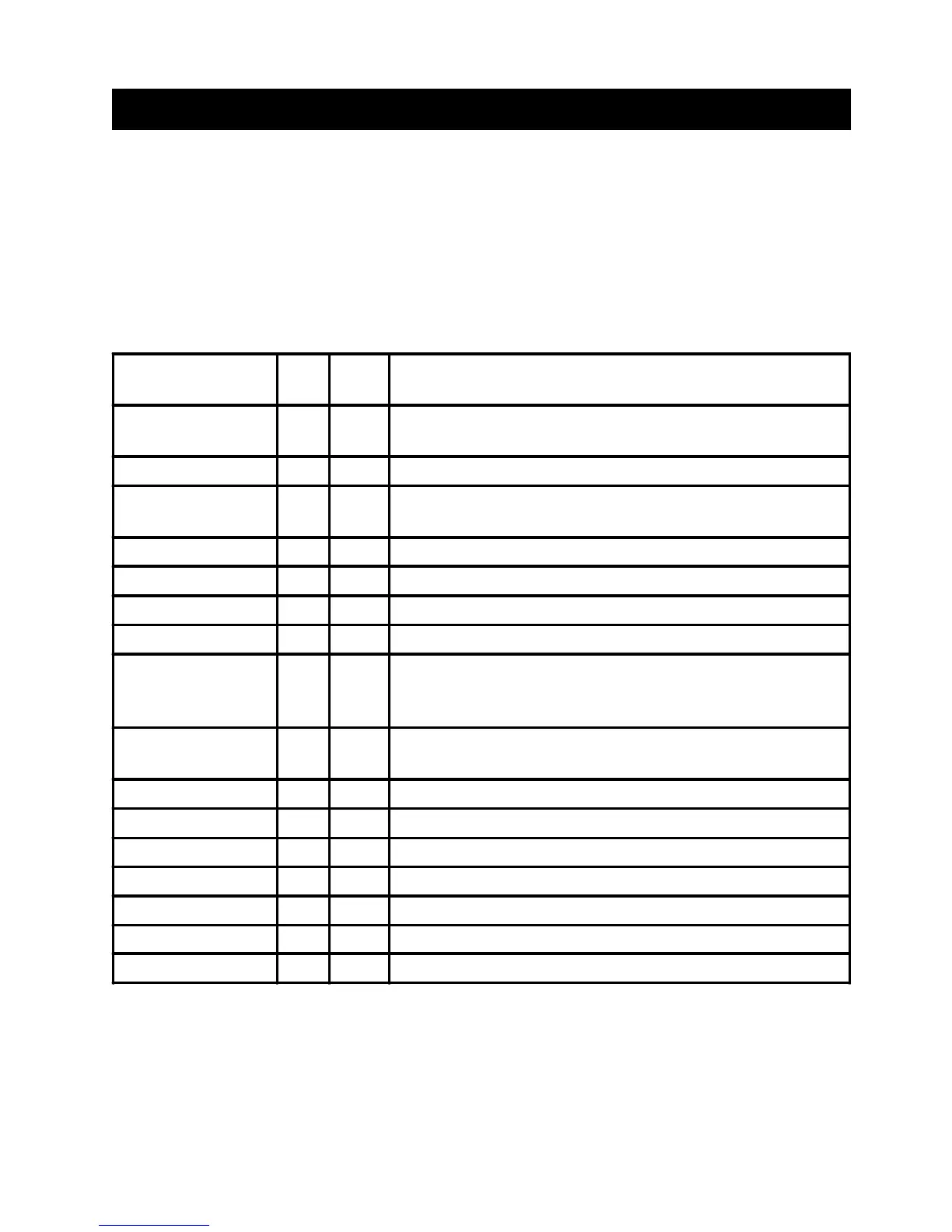
8. System Inputs Table
The Table below shows:
1) The Input Number that each System Input is mapped to for reporting to a Central Monitoring Station.
2) The Zone Lamp that each System Input is mapped to when viewing the “Fault History” (NEXT 13)
Zone Lamp Flashing = Currently in Alarm.
Zone Lamp On = Has been in alarm in the last 5 Arming periods.
3) A description of each type of System Alarm.
SYSTEM ALARM I/P
No.
Zone
Lamp
DESCRIPTION
AC Fail 101 1 The AC mains has failed, or has been absent for more than the
AC Fail delay time.
Low Battery 102 2 Battery voltage is too low to provide backup power if AC fails.
Cabinet Tamper 103 3 Un-authorised removal of cabinet cover or removal of the
cabinet from it's mounting surface.
Siren Monitor Alarm 104 4 The Siren speaker is disconnected from the Control Panel.
LAN Fuse fail 105 5 LAN fuse has blown. Short circuit or over-current condition.
Battery Fuse fail 106 6 Battery fuse has blown. Short circuit or over-current condition.
Comms Fail 107 7 System failed to report.
System Reset 108 8 The system has been powered down and powered up again.
Enter: PIN Code, <OFF> to Clear.
You should reset the Time and Date.
Keypad Lockout 109 9 System has registered 5 incorrect PIN code attempts in a row
and the Keypad is now locked out for a period of time.
Zone Self Test Fail 110 10 One or more Zone Inputs have failed the Zone Self Test.
Keypad Medical Alm 111 11 The Medical Alarm has been activated on a Terminal keypad.
Keypad Panic Alarm 112 12 The Panic Alarm has been activated on a Terminal keypad.
Keypad Duress Alarm 113 13 A Duress PIN code has been entered on a Terminal keypad.
Keypad Fire Alarm 114 14 The Fire Alarm has been activated on a Terminal keypad.
Test Report 120 - A Test report transmission has been sent.