Inner Range Inception Security Controller Installation Manual. Rev. 4.0
© 2016 - 2020. Inner Range Pty Ltd. 10 www.innerrange.com
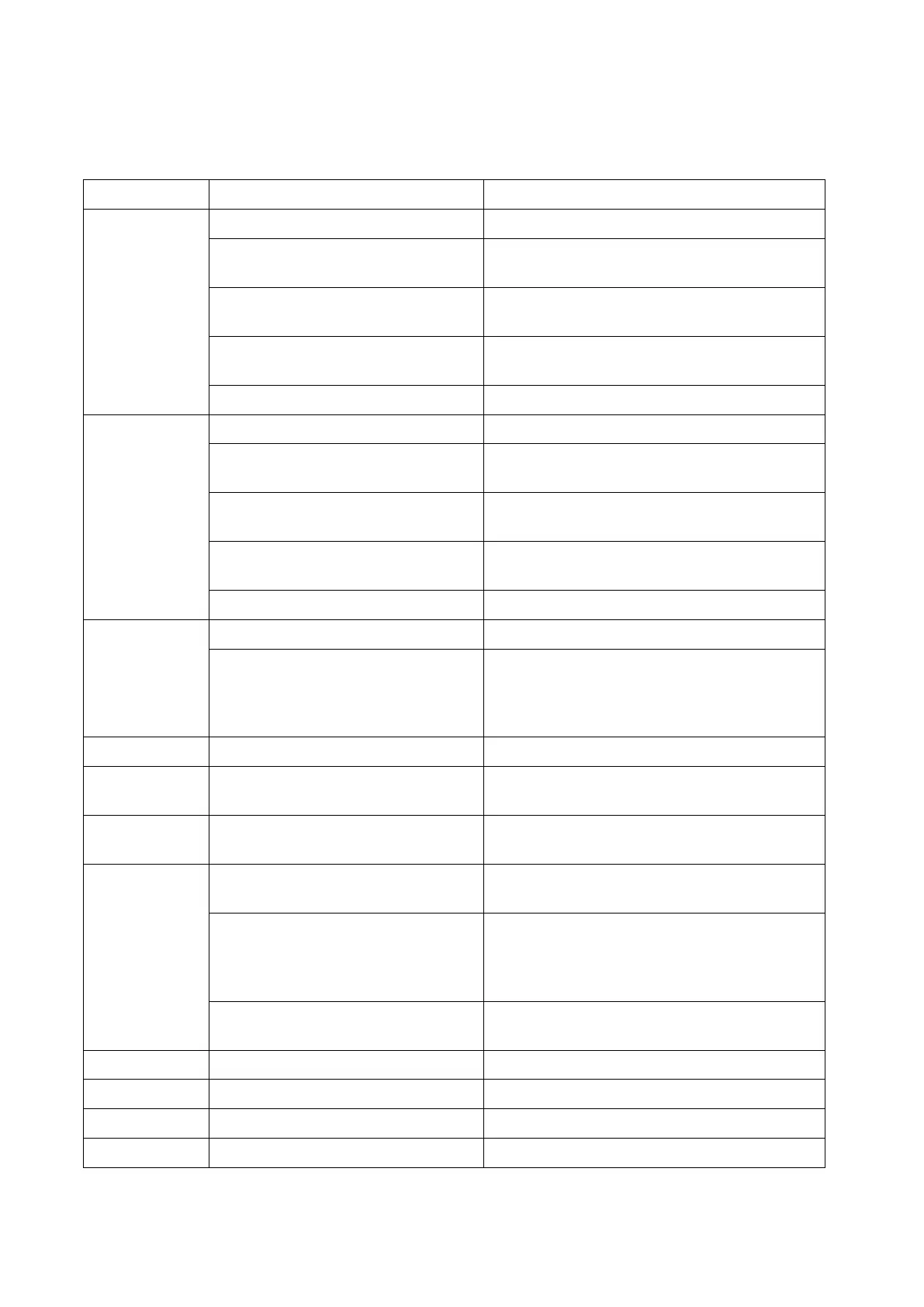
LED Status Indicators
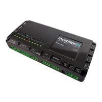
The Inception controller has 11 status LED’s to quickly identify the current operational status.
No DC IN connected. (Mains not present)
DC IN connected (Mains power present)
and within nominal voltage range.
Flash 2 Seconds (80% duty cycle)
Battery is present and in nominal voltage
range, and battery test is in progress.
Flash 0.4 Second (50% duty cycle)
DC IN is outside nominal voltage range (too
high or too low)
Flash 1 second (10% duty cycle)
Internal problem. Return for repair.
Battery connected, within nominal voltage
range and no battery test in progress.
Flash 2 Seconds (80% duty cycle)
Battery is present and in nominal voltage
range, and battery test is in progress.
Flash 0.4 Second (50% duty cycle)
Battery is outside nominal voltage range
(too high or too low)
Flash 1 second (10% duty cycle)
Internal problem. Return for repair.
Inception controller is running.
One or more of the power supply outputs
(VOUT) is shorted. Note that the green
LED remains flashing which results in an
alternating red & orange pattern.
SkyTunnel connection is established.
An Ethernet cable is connected and
Inception has an IP address.
There are one or more Alarms in the queue
to be sent to a monitoring station.
No Wi-Fi module present, or Inception not
configured to use Wi-Fi.
Wi-Fi module present, and Inception is on
Hotspot (Access point) mode.
Or, Wi-Fi module present, and Inception is
connected to a local Wi-Fi network.
Wi-Fi module present. Inception unable to
connect to a local Wi-Fi network.
OUT 1 is On (i.e. COM & NO connected)