Inner Range Inception Security Controller Installation Manual. Rev. 4.0
© 2016 - 2020. Inner Range Pty Ltd. 11 www.innerrange.com
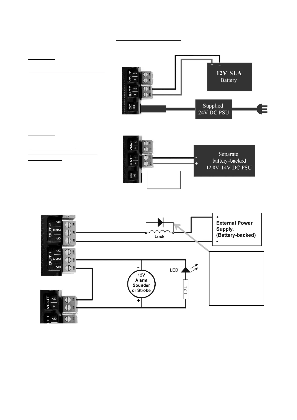
WIRING DIAGRAMS
Power Supply
OPTION 1.
Supplied 24V PSU and Battery.
OPTION 2.
Integriti 3A/8A PSU
or third party battery-backed
power supply.
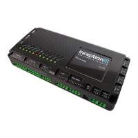
Output Relays (OUT1 – 4)
Lock or Solenoid Control. An External Power Supply is recommended to power inductive loads
to protect the controller, provide longer battery backup & minimise the possibility of earth loops.
Non-Inductive Loads. e.g. 12V Sounder, Beeper, Strobe, LED, etc. The Inception power
supply may be used to power these devices. Check that the additional current required by these
devices does not cause the Inception power supply output limits to be exceeded.