-105-
Introduction
■
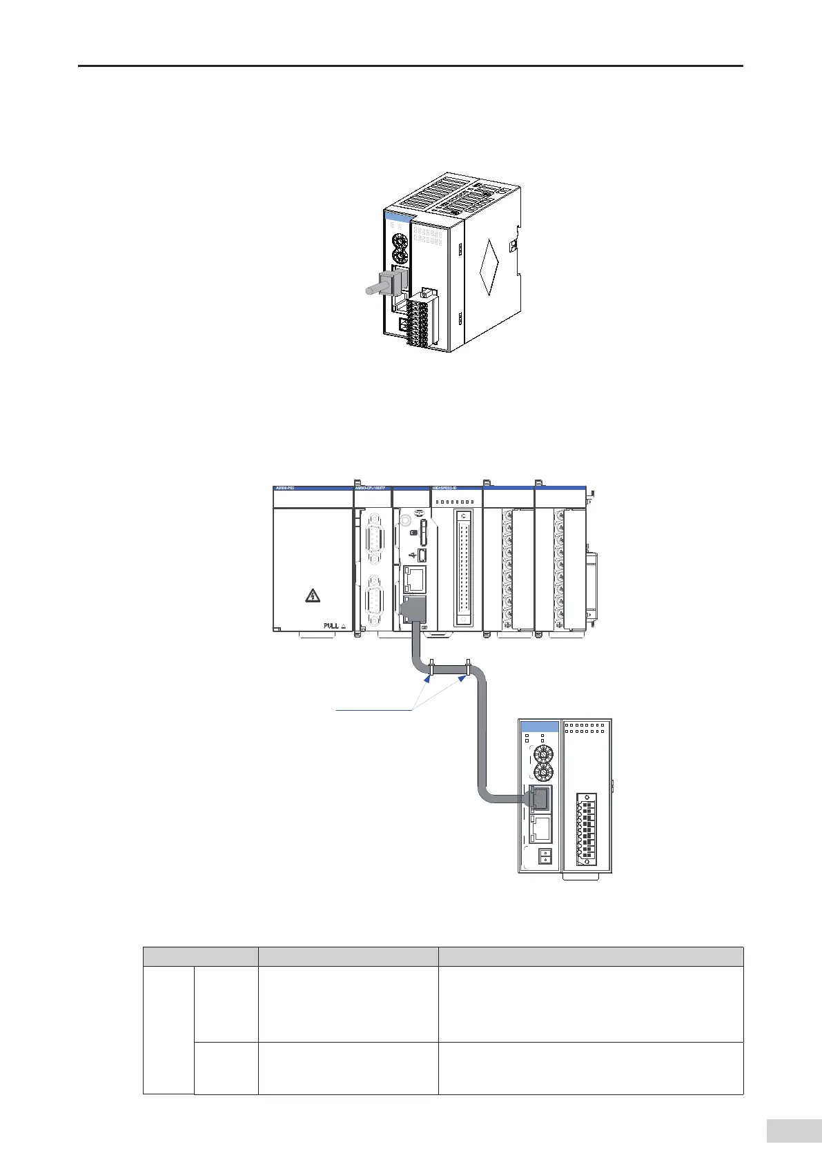
Communication connection
Hold the RJ45 connector (with a cable) and insert it to the EtherCAT socket of the communication
module until it clicks.
Figure 5-49 Communication connection
■
Communication cable xing requirement
To prevent communication cables from being aected by other tension and ensure communication
stability
,
x the cables on the device side before EtherCAT communication starts
,
as shown in the
following gure:
X1 IN
MFK
3940
2 1
CN5
CN1 RS485 CN2 CAN
CN3 EtherNET CN4 Ether CAT
STOPRUN
CANERR
CANRUN
BF
SF
ERR
RUN
0 1 2 3 7654
2 765410 3
4 5 6 73210
I
II
POWER
AM600
Risk of electric shock
Fix with
cable ties
0
1 2
3
4
5
6
7
1
2
3 4
5
6
7
X
Y
X2 OUT
X1X16
0V 24V
PWR RUN
SF ERR
AM600-0808ETNE
X1
X3
X5
X7
Y0
Y2
Y4
Y6
X0
X2
X4
X6
SS
Y1
Y3
Y5
Y7
COM
0
小心触电
Figure 5-50 Fixing the communication cable
■
Slave station module fault indication and solutions for EtherCAT communication
LED Indicator Description Solution
RUN
O
The EtherCAT master and slave
stations are in initialization state.
Check the conguration and parameter settings;
Check the communication address;
Check whether the network cable specications and
length meet the requirements.
Blinking
The EtherCAT slave station is not
in OP state.
Check the slave station conguration and check whether
any module is lost or faulty and whether any module
without conguration exists.

 Loading...


