-73-
Introduction
5.3.2 Wiring Precautions
1) Ensure that the external power supply is switched o during installation and wiring to avoid electric
shock and module damage.
2) Use a thick cable (max. sectional area: 2 mm²) as the 110 V/220 VAC power cable
,
twist the cable at
the terminal
,
and keep the power cable part connected to the terminal as short as possible to avoid
short circuit when the screw is loose.
3) Do not bind the 110 V/220 VAC power cable with the 24 VDC power cable
,
I/O signal cable
,
and
communication cable. Keep them as far from each other as possible.
4) After the power is switched on
,
the 24 VDC indicator is on
,
indicating that the power supply is
working properly. If the indicator is o
,
the power module input or the power module itself may be
faulty.
5) Use 16 - 22 AWG single-core or multi-core copper cables whose rated temperature is above 75 ℃ on
the wiring side. The tightening torque of the power terminal screw is 9.5 kg-cm (8.25 in-lbs).
5.3.3 Grounding
1) Connect the L and N (100 VAC to 240 VAC
,
50/60 Hz) lines to the L and N terminals of the power
module and connect the ground line of the power supply to the terminal of the module.
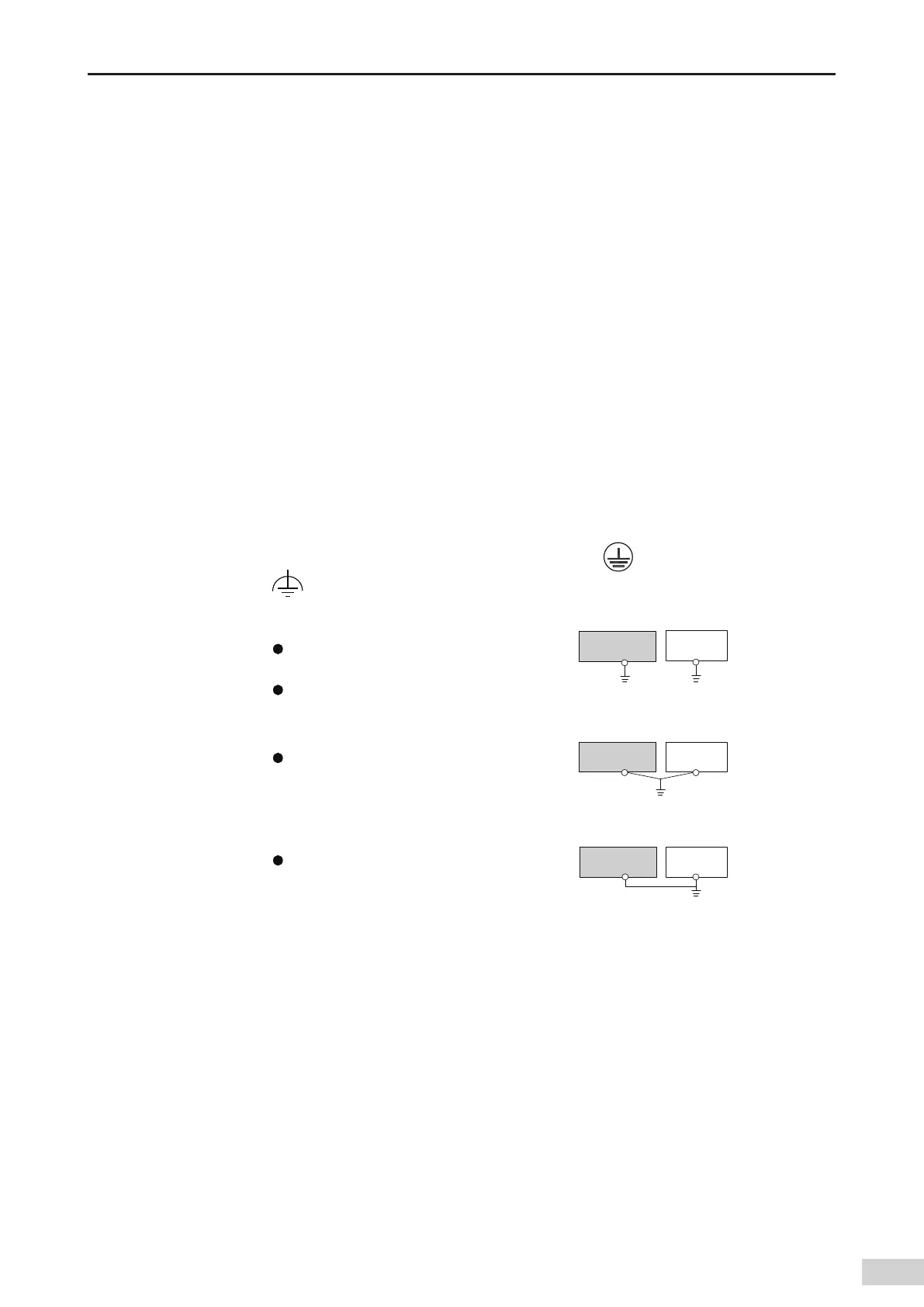
2) Connect the terminal of the power module to the nearest machine housing as the reference
ground. Comply with the following grounding requirements:
AM600-PS2
Other
device
AM600-PS2
Other
device
Other
device
AM600-PS2
Single point
grounding (optimal)
Common grounding
(allowed)
Grounding through
connection (prohibited)
The diameter of the ground cable cannot be smaller
than that of the L and N cables on the power side;
Use single point grounding when multiple devices are
used simultaneously;
When single point ground is not allowed, use common
grounding as shown on the right;
Do not connect to the ground as shown on the right!
Figure 5-11 Power module grounding requirements
3) Use a cable thicker than 2 mm² as the grounding cable and ensure that the grounding impedance is
less than 100 Ω.

 Loading...


