EasyManua.ls Logo

Inovance AM600 Series - INOVANCE Warranty Agreement

Inovance AM600 Series
133 pages
To Next Page IconTo Next Page
To Previous Page IconTo Previous Page
Loading...
-27-
Introduction
2 External interfaces of the CPU module
MFK
RUN/ STOP
3940
2 1
CN5
CN1 RS485
CN2 DP/CAN
CN3 EtherNET CN4 EtherCAT
CANERR
CANRUN
BF
SF
ERR
RUN
0 1 2 3 7654
2 765410 3
4 5 6 73210
I
II
DB9(CN1)
female connector
SD card
interface
LED
DB9(CN2)
female connector
Network port (CN4)
Network
port (CN3)
USB port
High-speed
I/O interface
I/O indicator
DIP switch
System
indicators
MFK button
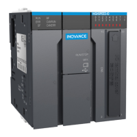
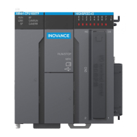
Figure 3-3 Interfaces of the CPU module (AM600-CPU1608TP as an example)
24 V power input
terminal
Grounding
switch
DIP switch of
communication
termination resistor
(Left side)
Local expansion
bus interface
(Right side)
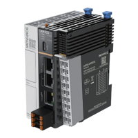
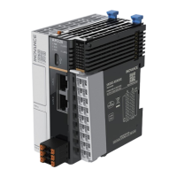
Figure 3-4 Interfaces of the CPU module (AM600-CPU1608TP is used as an example)

Table of Contents

Other manuals for Inovance AM600 Series

Related product manuals