-45-
Introduction
2) Module interface description
EtherCAT
OUTI N
SF
BF
POWER
RUN
24V
5V
GND
GND
ECT
Signal indicator
EtherCAT communication port
Local
expansion
back-end
interface
Internal 24 V
power input
terminal
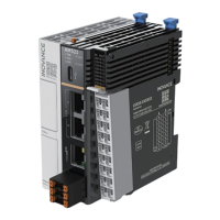
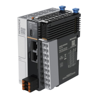
Figure 3-23 Interfaces of EtherCAT communication module (AM600-RTU-ECT/AM600-RTU-ECTA)
No. Interface Name Function
1
IN EtherCAT input interface
OUT EtherCAT output interface
2 Signal indicators
POWER: power indicator
RUN: running indicator
SF: expansion bus error indicator
BF: communication error indicator
3
Local expansion module back-end
interface
Connects to the back-end module and does not support hot
swap. For details about the use
,
see
"Chapter 4 Installation"
.
4 Internal 24 V power input terminal
Connects to the power module and does not support hot
swap. For details about the use
,
see
"Chapter 4 Installation"
.
3) Dimensions (mm)
EtherCAT
OUTIN
SF
BF
POWER
RUN
32.0
90.0
95.0
ECT
EtherCAT
OUTIN
SF
BF
POWER
RUN
32.0
90.0
95.0
ECT
Figure 3-24 Dimensions of EtherCAT communication module (AM600-RTU-ECT/AM600-RTU-ECTA)
 Loading...


